Prop Pillow: Smart Comfort System
Role: Hardware Engineer & Circuit Designer | Collaborative Project with 4 Classmates | Duration: Dec 2021 - Jun 2022
Prop Pillow is an innovative smart pillow system that provides dynamic comfort through real-time adjustable firmness. Building on experience from previous projects involving solenoids and smart control systems, our team developed a compact, battery-powered solution that seamlessly combines hardware and software for optimal user comfort.
Prop Pillow Demonstration: Real-time Firmness Adjustment
Adaptive Support
Real-time inflation and deflation for customizable comfort
Quiet Operation
Low noise air pump with vibration dampening
Long Battery Life
8-10 hours of intermittent use on a single charge
Wireless Control
RF remote for easy firmness adjustment
Development Process
Research & Ideation
December 2021 - January 2022
- Finalized core concept
- Conducted preliminary tests
- Selected key components
Initial Prototyping
February 2022
- Created first breadboard circuit
- Developed 3D-printed casing
- Tested component integration
Iteration & Testing
March - April 2022
- Added RF remote control
- Improved noise reduction
- Conducted user trials
Final Refinements
May - June 2022
- Enhanced solenoid design
- Optimized battery life
- Finalized production design
Technical Implementation
Power System
- 12V Li-ion Battery Pack (3S)
- 8-10 Hour Battery Life
- Integrated Charging Circuit
Control System
- 433MHz RF Remote Control
- Arduino-based Logic
- PWM Motor Control
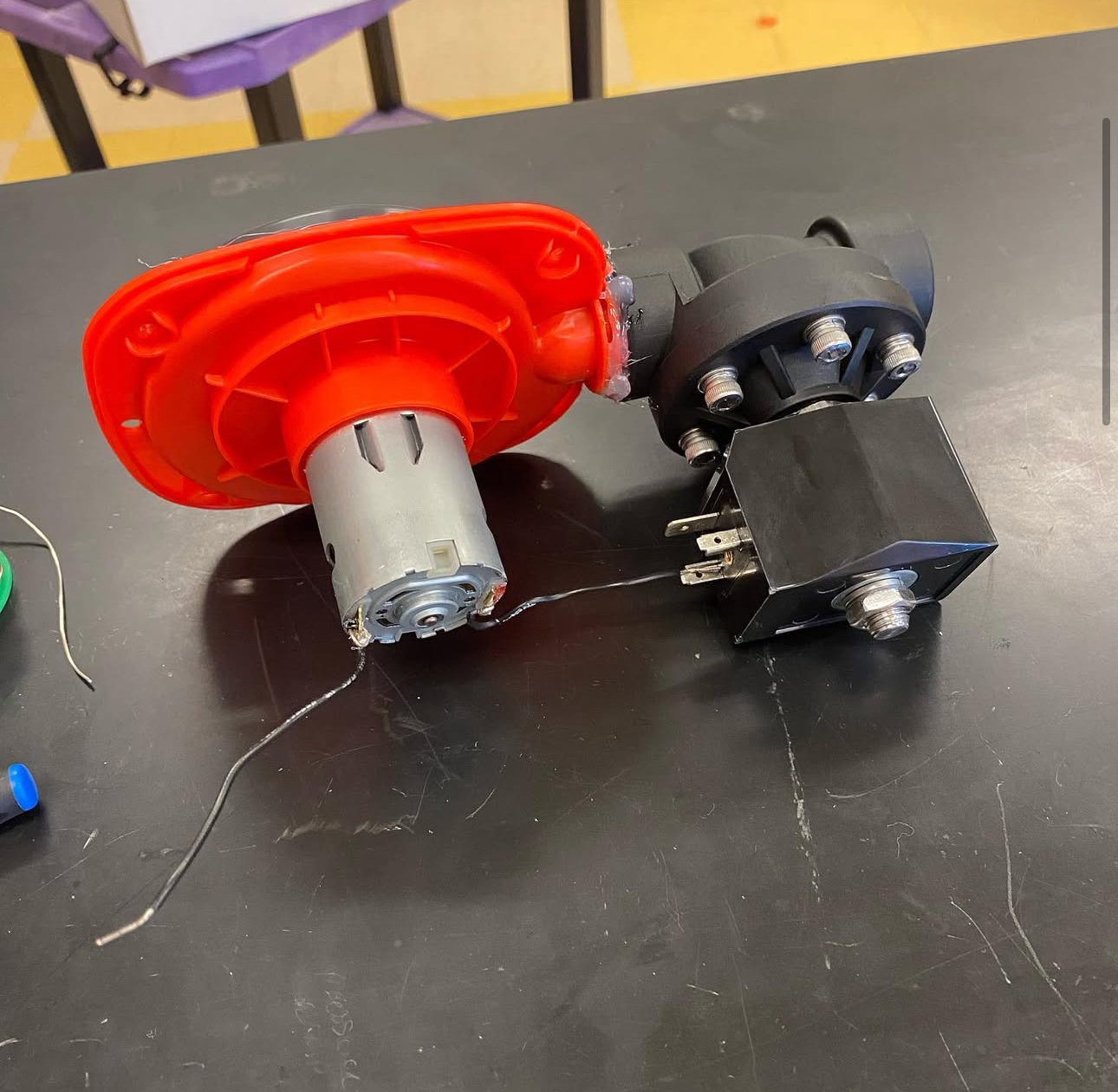
Air System
- 12V DC Air Pump
- Normally Closed Solenoid
- Check Valve Protection
Prototyping & Iterations
Mechanical Design
- 3D-printed housing (12cm × 8cm × 6cm)
- Rubber dampeners for noise reduction
- TPU/PVC air bladder design
Noise Reduction
- 15-20 dB noise reduction
- Sound-dampening foam
- Vibration isolation mounts
User Interface
- Intuitive RF remote
- LED status indicators
- Backup manual controls
Team Structure & Roles
Developed as part of a five-person team at Indiana University, this project exemplifies collaborative engineering at its best. Our diverse team brought together complementary skills in hardware, software, and mechanical engineering, with each member taking ownership of critical aspects of the project.
Lead Hardware Engineer
My Role: Circuit Design & Integration
- Power management system design
- RF communication integration
- Battery performance optimization
Software Lead
Control Systems & Programming
- Core control algorithms
- RF protocol development
- System integration
Mechanical Design
Physical Implementation
- 3D modeling & printing
- Acoustic optimization
- Assembly design
Project Coordination
Management & Planning
- Sprint planning
- Resource management
- Documentation
Quality Assurance
Testing & Validation
- Test protocol design
- User experience research
- Performance validation
Each team member brought unique perspectives and skills to the project, fostering an environment of collaborative innovation. Regular team meetings and agile development practices ensured effective communication and rapid iteration on design improvements.
Project Gallery
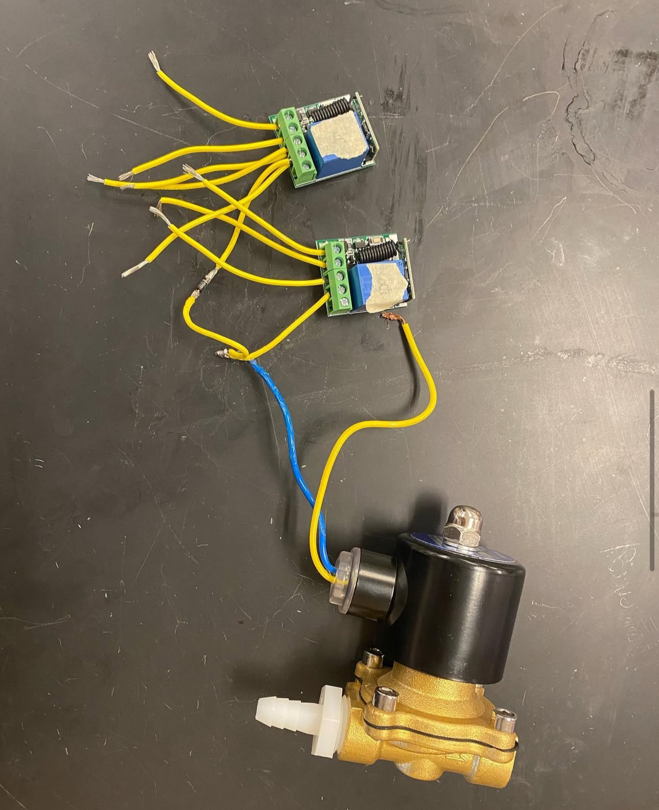
Control Unit Assembly
Internal Components
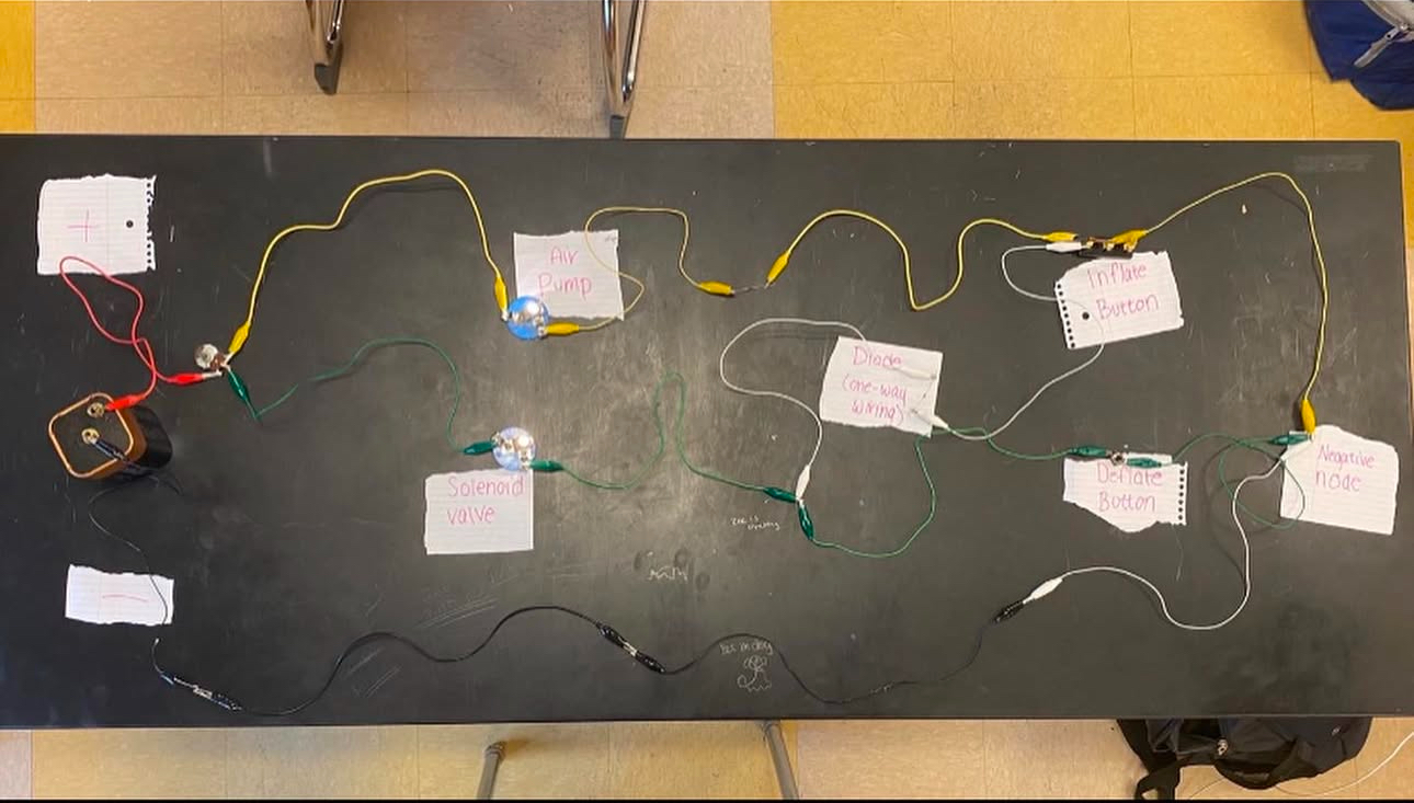
Circuit Implementation
Wireless Control Module
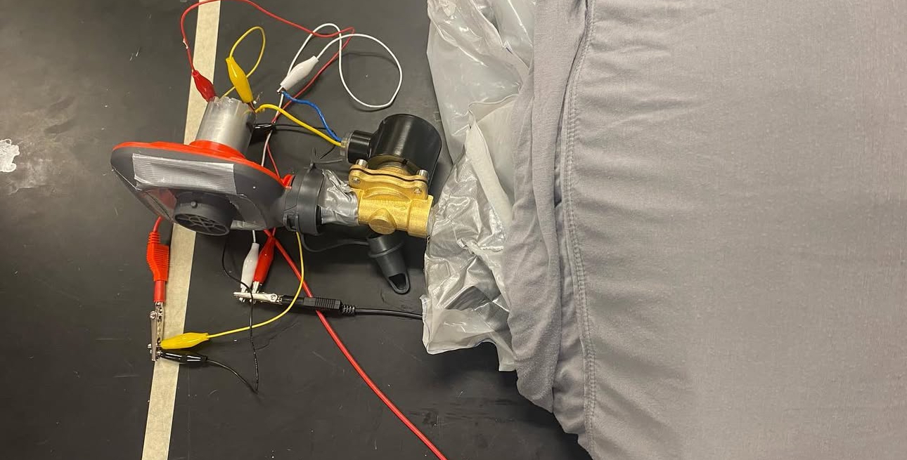
Final Assembly
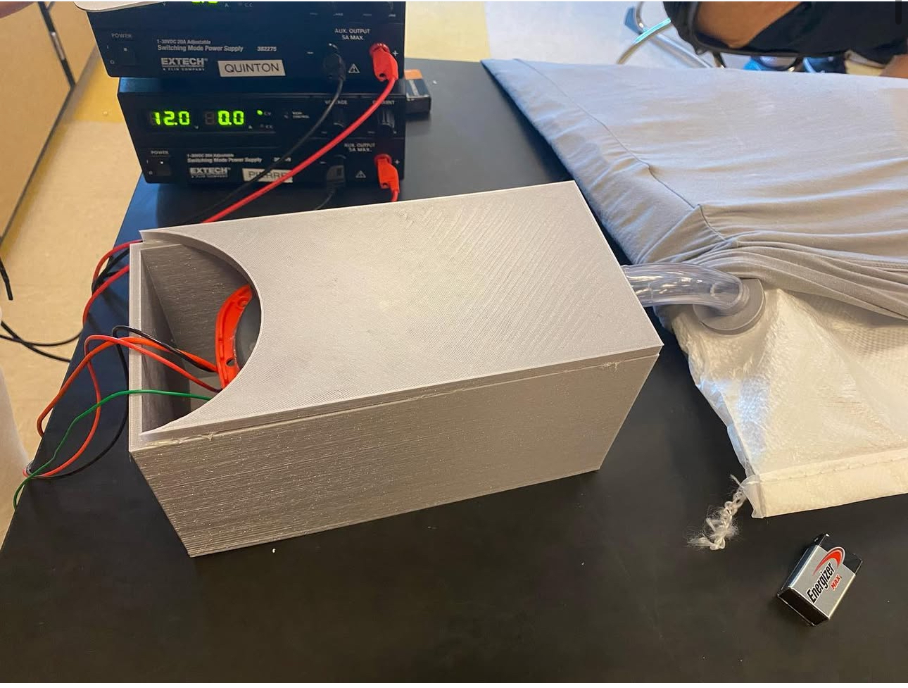
Complete System
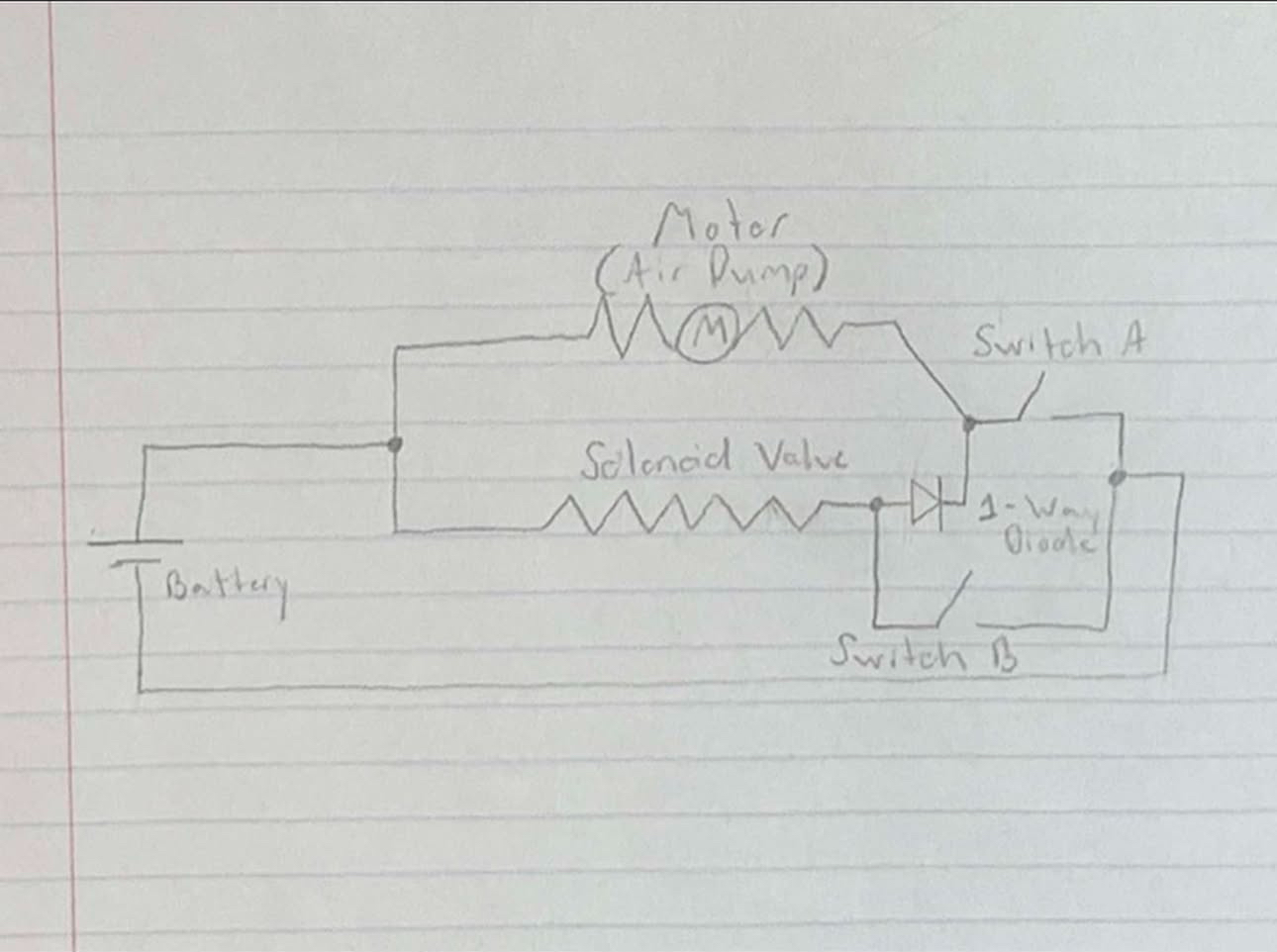
Technical Documentation
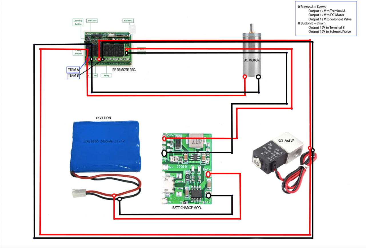
Detailed Circuit Diagram and Component Layout
Downloads & Resources
3D Models
- Main Housing (Part Studio 2)
- Pump Mount (Part Studio 3)
- Fan Blade (Bd920FanBlade)
Documentation
- Circuit Schematics
- Assembly Guide
- User Manual