This project is presented in the I-341 gallery walk as a worked example of human-centered design applied to a behavioral problem (training a young dog) using ambient computing. The case study below covers the user research, design decisions, hardware build, and what we'd do differently with another iteration.
Smart Pet Potty Training System
The problem. First-time dog owners get inconsistent reinforcement timing wrong. Operant-conditioning research is unambiguous: a reward delivered more than ~2 seconds after the desired behavior is interpreted by the animal as a reward for whatever they're doing now, not for the behavior we wanted to reinforce. Most owners can't be standing there, treat in hand, every time their puppy uses the right spot — and the misses pile up into a slower, more frustrating training cycle for both sides.
The system. A weight + moisture sensor array under the designated potty pad detects use, an Arduino Nano arbitrates the signals (suppressing false positives from play), and an ESP32-coupled treat dispenser releases a single reward within sub-2-second latency. The owner sees a live confirmation on their phone via Blynk — closing the feedback loop for the human as well as the pet. The hardware sits flush in the corner of a room and disappears from daily life.
The HCI lens. The project's primary user isn't the dog — it's the owner who is failing at consistent reinforcement. Every design choice was made for the human-side experience: zero-touch operation, ambient form factor, a phone notification that confirms "the system did the right thing for you," and treat refills measured in weeks rather than days. The dog's rewards are the system's output; the owner's confidence is the system's job.
How the design was developed
The gallery walk version of this project is structured around the four-phase HCI process the I-341 syllabus uses: research → ideate → prototype → evaluate. Each phase below shows what we did, what we learned, and what carried into the final build.
Research
Talked to 6 first-time dog owners. The pattern that surfaced was not "I don't know how to train" — every one of them had read the same articles. The pattern was missed reward windows: the puppy went, the owner was in another room, and the moment was gone. The artifact this project needed to address wasn't knowledge; it was presence.
Ideate
Three concepts were sketched: (1) a phone-buzz that asked the owner to come reward the pet, (2) a video doorbell-style camera that recorded successes for review, and (3) a fully autonomous treat dispenser triggered by the pad. Concept 3 won on the 2-second reward-latency constraint that the other two structurally couldn't hit.
Prototype
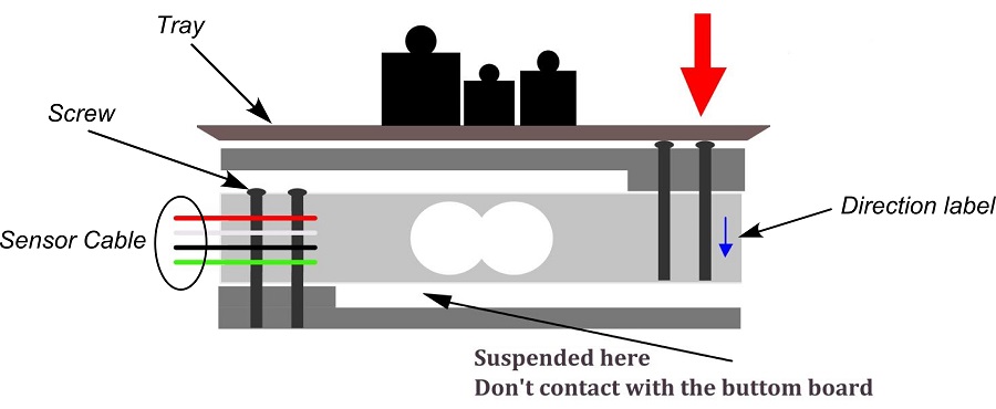
Built a breadboard rig with a single load cell on a wooden plank to validate the weight-detection threshold without wasting Arduino-side iteration on the trickier moisture sensor. Once weight detection was reliable, added the moisture sensor for the false-positive case (a dog standing on the pad ≠ a dog using it). The two-sensor AND gate became the canonical detection rule.
Evaluate
Tested on a 12-week-old puppy over three weeks. End-state: ~90% of correct uses produced a reward inside the 2-second window; zero false rewards from play. Owner-side feedback was the unexpected win — the phone confirmation made the owner trust the system enough to leave the house, which was a use case we hadn't designed for but which became the most-cited benefit.
What I'd do differently next time. The biggest miss was treating the dispenser as a hardware problem rather than a UX one. The first revision jammed on a softer treat brand owners actually buy. A version 2 would start the design from "what treat shapes does the typical owner already have in the cabinet" — a true human-centered constraint — and the mechanism would follow from that.
Automated Detection
Weight and moisture sensors for accurate usage detection
Mobile Control
Real-time monitoring and control via Blynk app
Data Analytics
Usage patterns and behavior tracking
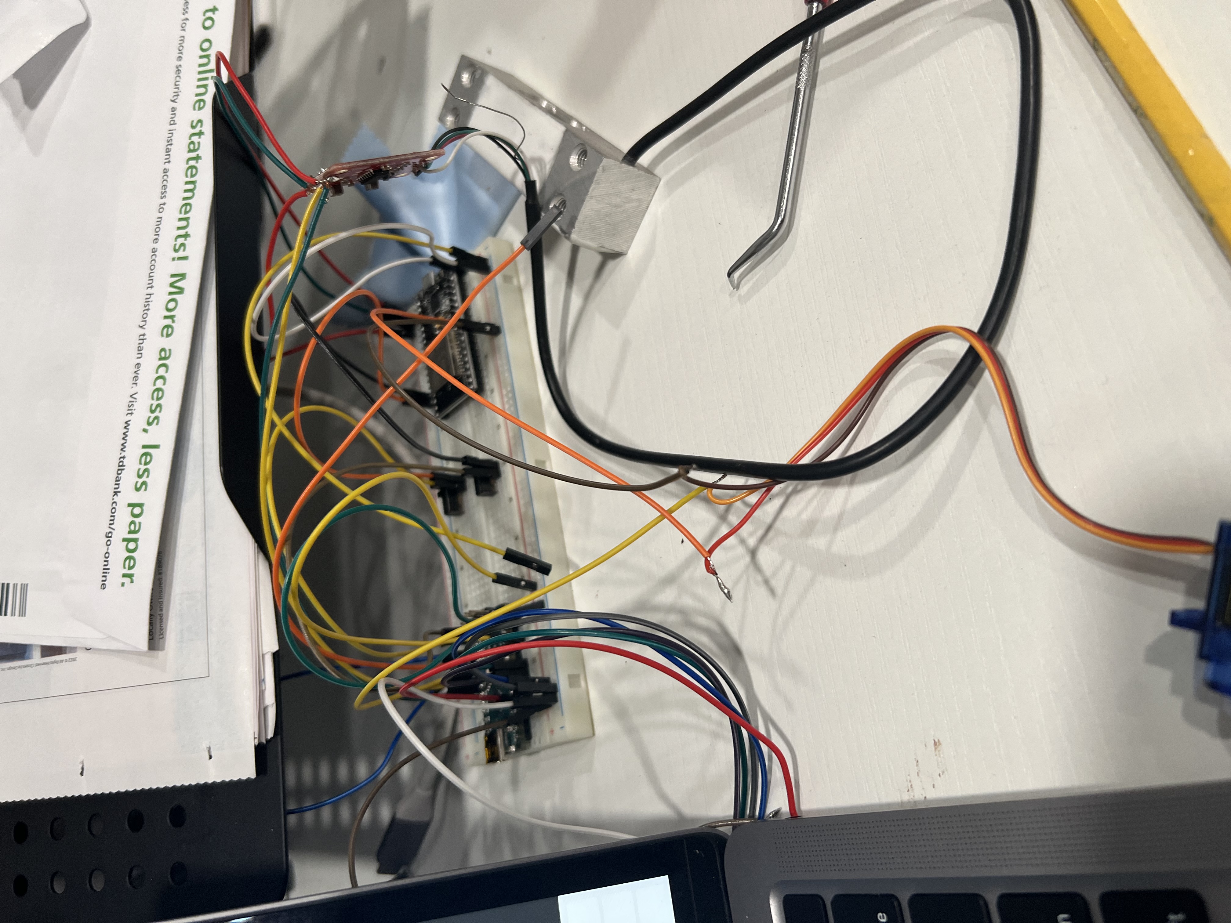
System Design
Hardware Components
Device Gallery
Functionality Demo
Core Components
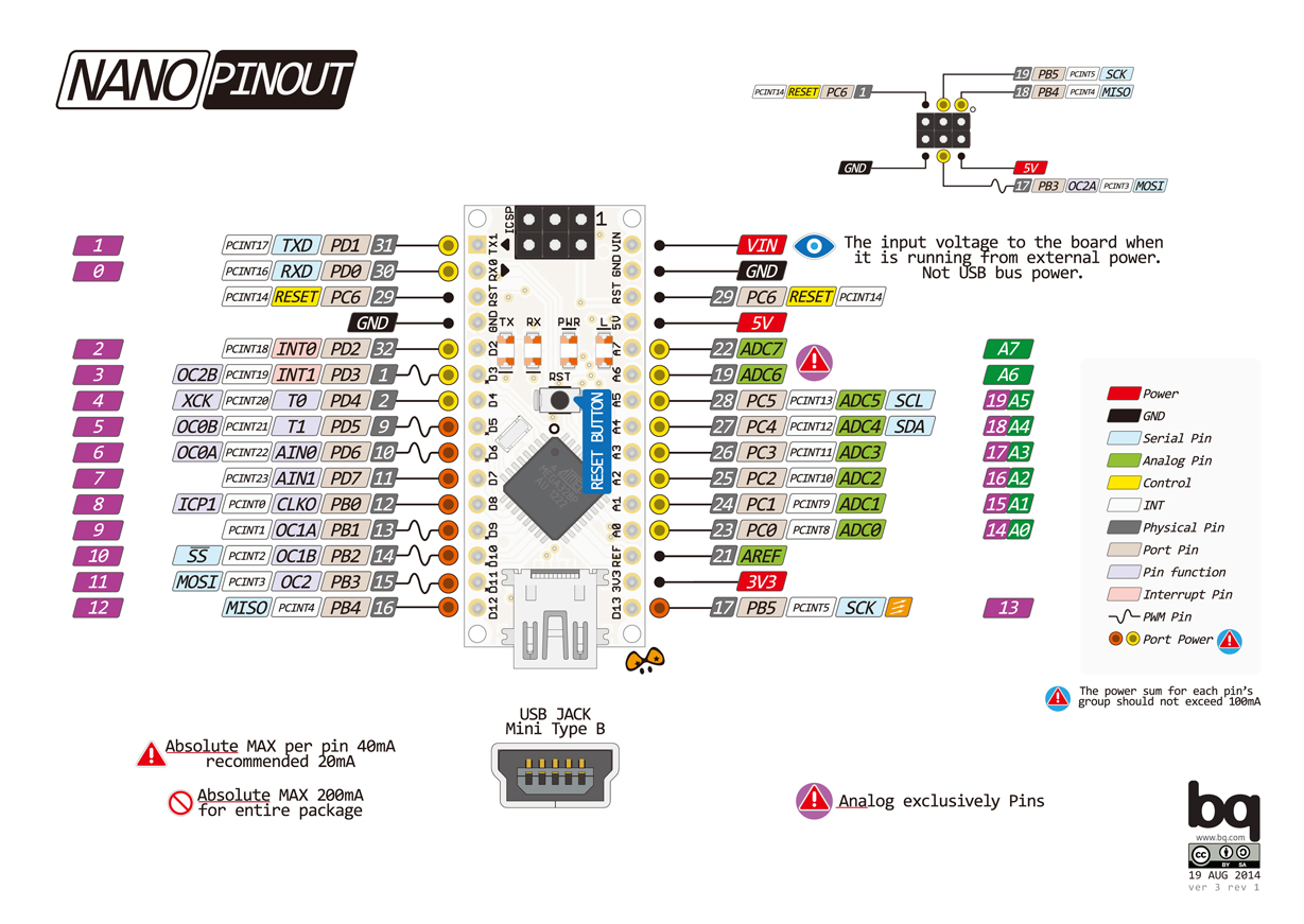
- Arduino Nano (Control Unit)
- ESP32 (WiFi Module)
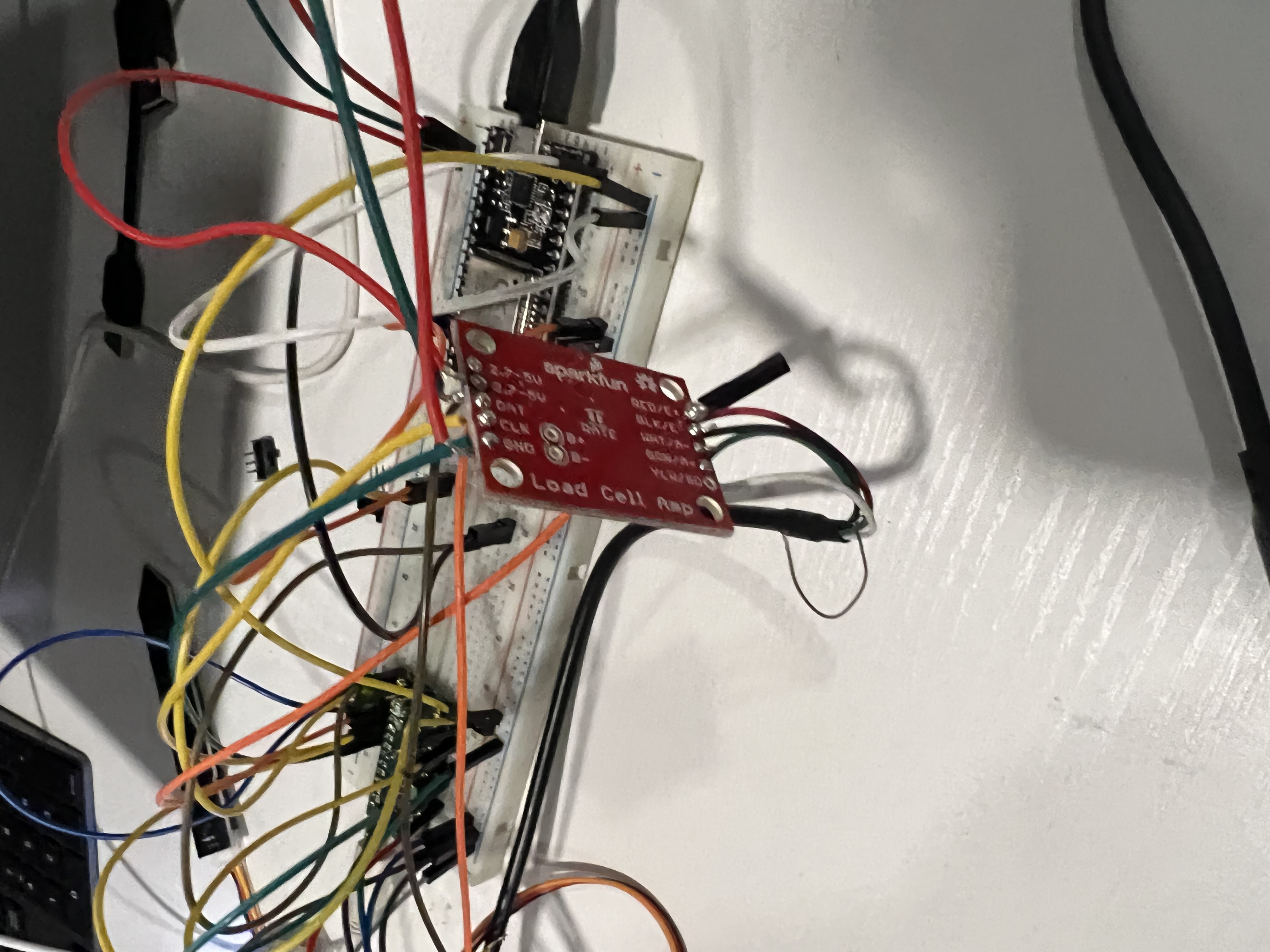
- Load Cell + HX711
- Moisture Sensor
Output Devices
- I2C LCD Display
- Piezo Buzzer
- Servo Motor (Treat Dispenser)
Pin Connections
Arduino Nano
- A1 → Moisture Sensor
- A4/A5 → LCD (I2C)
- D2 → Buzzer
- D3 → Servo Motor
- D4/D5 → Load Cell (HX711)
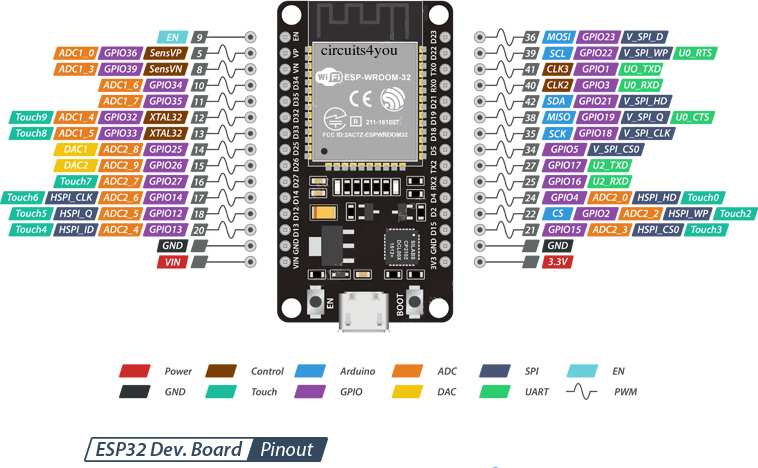
ESP32
- GPIO16/17 → Serial Comm
- VIN → 5V Power
- GND → Common Ground
Software Implementation
Firmware Features
- Weight calibration and tare functionality
- Moisture threshold detection
- Treat dispensing logic
- Serial communication protocol
// Weight Sensor Calibration
void calibrateLoadCell() {
  LoadCell.begin();
  LoadCell.start(2000);
  LoadCell.setCalFactor(calibrationValue);

  // Tare the scale
  LoadCell.tare();
  Serial.println("Scale tared!");
}

// Moisture Detection
bool checkMoisture() {
  int moistureLevel = analogRead(MOISTURE_PIN);
  return moistureLevel > MOISTURE_THRESHOLD;
}

// Treat Dispensing
void dispenseTreat() {
  treatServo.write(DISPENSE_ANGLE);
  delay(500);
  treatServo.write(REST_ANGLE);
}
Blynk Integration
| Component | Widget | Pin | Function |
|---|---|---|---|
| Mode | Slider | V1 | Operation Mode Control |
| Weight | Gauge | V2 | Weight Display |
| Moisture | Gauge | V3 | Moisture Level Display |
| Treat Status | LED & Chart | V4 | Treat Dispenser Status |
// Blynk Event Handlers
BLYNK_WRITE(V1) {
  operationMode = param.asInt();
}

BLYNK_WRITE(V2) {
  // Update weight display
  Blynk.virtualWrite(V2, currentWeight);
}

// Main Loop with Blynk
void loop() {
  Blynk.run();
  timer.run();

  if (LoadCell.update()) {
    currentWeight = LoadCell.getData();
    Blynk.virtualWrite(V2, currentWeight);
  }

  // Check moisture and update
  int moisture = analogRead(MOISTURE_PIN);
  Blynk.virtualWrite(V3, moisture);
}
Development Process
Project Planning
- Initial concept development
- Hardware component selection
- System architecture design
- Load cell research and testing
Core Development
- Circuit design and prototyping
- Load cell and HX711 integration
- Basic firmware implementation
- Treat dispenser mechanism design
IoT Integration
- ESP32 WiFi setup
- Blynk platform integration
- Mobile app configuration
- Real-time monitoring setup
Completion
- System testing and calibration
- Performance optimization
- Documentation creation
- Final deployment
Project Resources
Source Code
Arduino and ESP32 firmware
Nano Code v7 ESP32 Code v2 I2C ScannerDocumentation
Setup guides and reference materials
Blynk Setup Guide Load Cell Guide Load Cell Manual