CoilCap — Modular Cable Storage
Every charging cable in a drawer, coiled, labeled and stacked. Five box widths, three heights, slide-in printed labels, dovetailed baseplates, wall mounts and drawer trays — 67 parts, all generated from a single parametric source file.
The interesting part isn't the boxes. It's that the whole system is built like software: one source of truth, a build script that renders every part, and an automated test suite that refuses to publish a part it can't verify. Three real design bugs were caught by those tests before a gram of filament was spent.
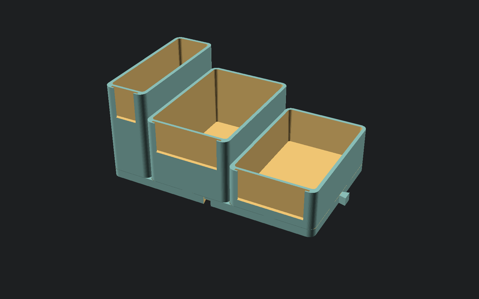
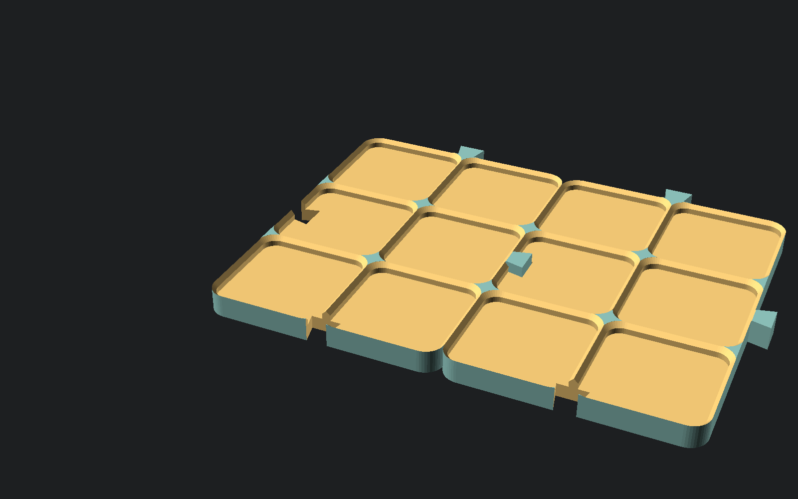
A short, a standard and a tall box seated on one 5×3 baseplate.
One grid, fifteen boxes
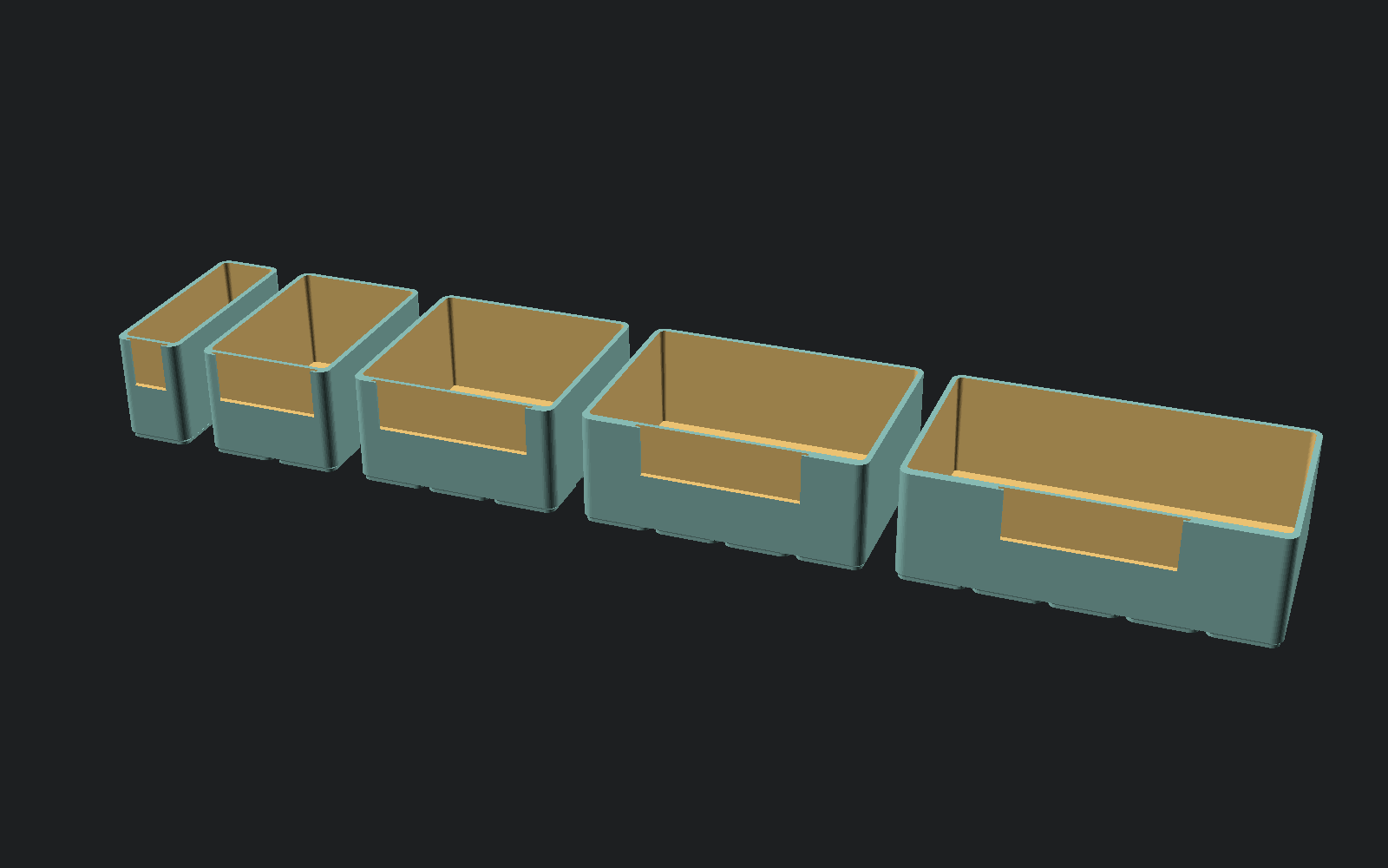
Everything sits on a 25 mm grid. Boxes are a constant 75 mm deep and 1–5 units wide, in three heights that all stack on each other. The largest part is 130 mm across, which clears a 150 mm bed with room for a brim.
| Size | Footprint | Interior width | Fits |
|---|---|---|---|
| S | 25 × 75 mm | 19.4 mm | One coiled phone cable |
| M | 50 × 75 mm | 44.4 mm | USB-C bundle, earbuds |
| W | 75 × 75 mm | 69.4 mm | Laptop brick |
| L | 100 × 75 mm | 94.4 mm | Coiled HDMI, ethernet |
| XL | 125 × 75 mm | 119.4 mm | Wall warts, adapters |
Heights are 25, 40 and 55 mm, giving 21.2 / 36.2 / 51.2 mm of usable depth. All fifteen width × height combinations are included — twice over, because every one comes in a straight and an angled version.
Angled bins
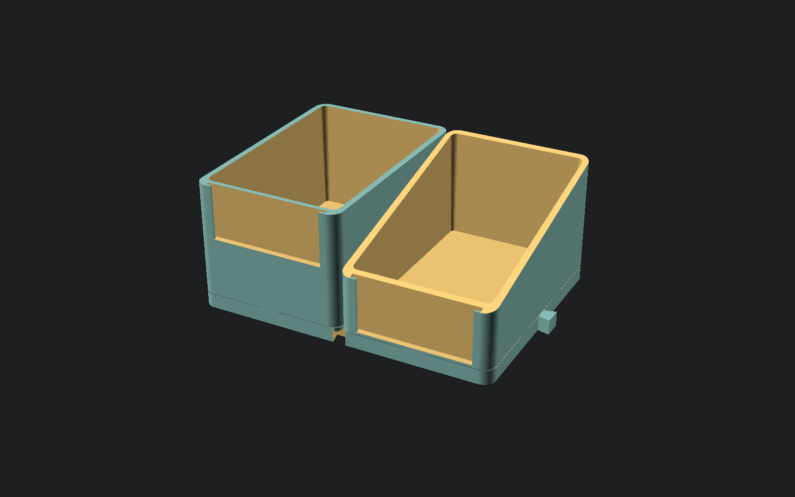
The angled variant drops the front wall to half height and slopes the opening back up to the full rim, so you can see and grab a coiled cable without lifting the box above it out first. The cut is a single upward-facing plane, so like everything else here it prints with no support material. The label pocket moves down with the front wall and takes the same cards.
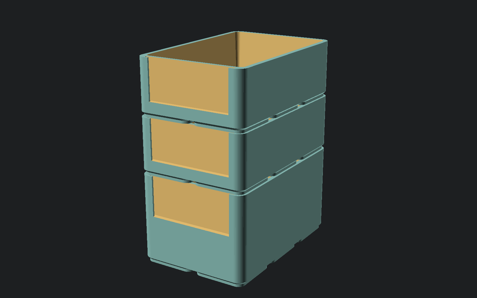
One trade-off worth knowing: an angled bin has no front rim, so nothing stacks on top of it. Put them on a baseplate, in a tray, or at the top of a stack — an angled bin stacked onto a straight box works fine, just not the other way round.
Three details that make it work
A three-stage foot
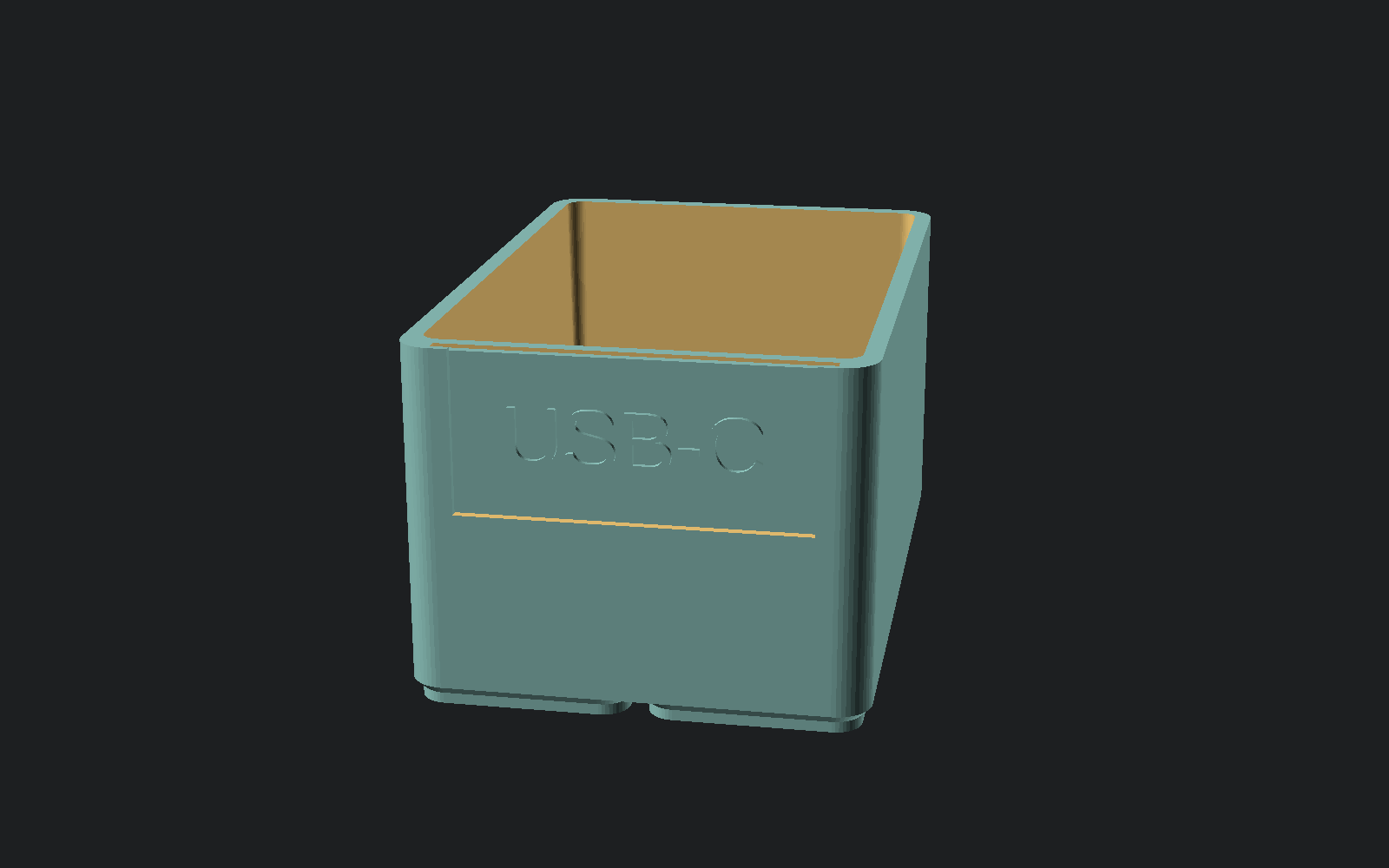
Each 25 mm cell has its own foot: a 1.2 mm straight section inset 1.0 mm, then a 1.0 mm chamfer out to full width. The straight part locates in the baseplate bore. The gaps between the feet are what the baseplate's webs sit in — which is why a five-wide box drops flat onto a grid instead of rocking on the ridges between sockets.
Stacking without a lid
The top of every wall carries an 0.8 mm outward chamfer. Stacked box-on-box, the outer foot perimeter lands on the rim below with 1.0 mm of lateral engagement and the chamfer funnels it into place. Any box is a lid for the box under it.
A label pocket you can actually reach
The front wall is 4.4 mm thick and carries a 2.0 mm pocket, open at the front and at the top. A 1.0 mm card slides down into it, retained by 2.0 mm lips at each edge with the middle left exposed — so you can read it and thumb it back out. The first version of this put the card behind a solid front plate, which looked fine in CAD and would have been completely opaque in PLA.
Testing physical parts like software
Failed prints are slow. A bad part costs two hours and 40 grams before you find out. So the build refuses to write a part it cannot vouch for, and the joints are tested before anything is sliced.
Per-part checks
Every part must be a single closed manifold body — CGAL reports it as simple with exactly one solid volume, and an independent mesh pass confirms the STL is watertight with consistent winding (every directed edge used once, its reverse present). The bounding box must clear the 150 mm build envelope with margin.
Assembly checks
For each pair of mating parts the harness renders their intersection in the assembled position and measures its volume. Two things have to hold at once:
clearance  — in the nominal position the overlap must be zero,
             or the parts physically cannot go together

engagement — pushed 0.4-0.5 mm the overlap must become non-zero,
             or the joint is so loose it never actually touches
The second direction is the one people skip, and it's the one that matters. A clearance test on its own passes a dovetail that is three millimetres too small — it never touches anything, so it never collides.
What it caught
These were all found by the tests, not by printing:
- Baseplate webs colliding with multi-cell box bodies. The ridges between sockets stood 1 mm proud of where the feet merged, so any box wider than two units sat on the ridges instead of the sockets. Fixed by restructuring the foot into three stages.
- Dovetail slots cut facing the wrong way. A 180° rotation put every slot outside the plate instead of into it, so plates could not join at all — and the geometry still rendered perfectly cleanly.
- Label text running under the retaining lips on the smallest card, which would have jammed it in the pocket.
A fourth bug — the cavity floor cutting straight through the taller feet and orphaning the centre foot as a loose fragment — was caught by the per-part manifold check, which reported two disconnected bodies where there should have been one.
Print settings
Designed and verified against a FlashForge Adventurer 3C — 150 mm cube, 0.4 mm nozzle, 240 °C hot end, enclosed. Any printer with a 150 mm bed will run it.
| Setting | Value | Why |
|---|---|---|
| Material | PLA | PETG works at 235/70; 240 °C max leaves no headroom for ABS |
| Layer height | 0.2 mm | 0.3 mm on tall boxes saves about a third of the time |
| Perimeters | 4 | Makes the 2.8 mm walls solid so infill never touches them |
| Infill | 15 % | Only the floor slab uses it |
| Supports | Off | Nothing overhangs past 45° |
| Raft | Off | FlashPrint defaults it on; use a brim if a corner lifts |
Print this first: one M box, one 2×3 baseplate, one label card. That trio exercises every fit in the system — foot in socket, box on box, card in pocket — in about ninety minutes. If anything is tight, nudge one constant and re-run the build; the fit tests will tell you immediately if you broke a joint.
Free, MIT licensed, no signup
CoilCap — complete system
All 67 STLs, the parametric OpenSCAD source, the build and verification scripts, the assembly test harness, and full documentation.
Download free
Want a different grid pitch, wall thickness or label size? Change the constant at the top of
coilcap_system.scad and run python3 build_all.py. It regenerates and
re-verifies the whole set. python3 fitcheck.py re-runs the assembly tests.