Solo build · HW + SW Open source · MITGravely ZT X 52 · 2026
Autonomous Zero-Turn Mower
A ground-up retrofit that turns a commercial gas zero-turn into a self-driving, iPad-controlled
robot. RTK GPS, LiDAR, cameras, and on-device AI — engineered end-to-end across
hardware, firmware, control software, and parametric CAD, and reproducible on any zero-turn by
re-measuring a handful of dimensions.
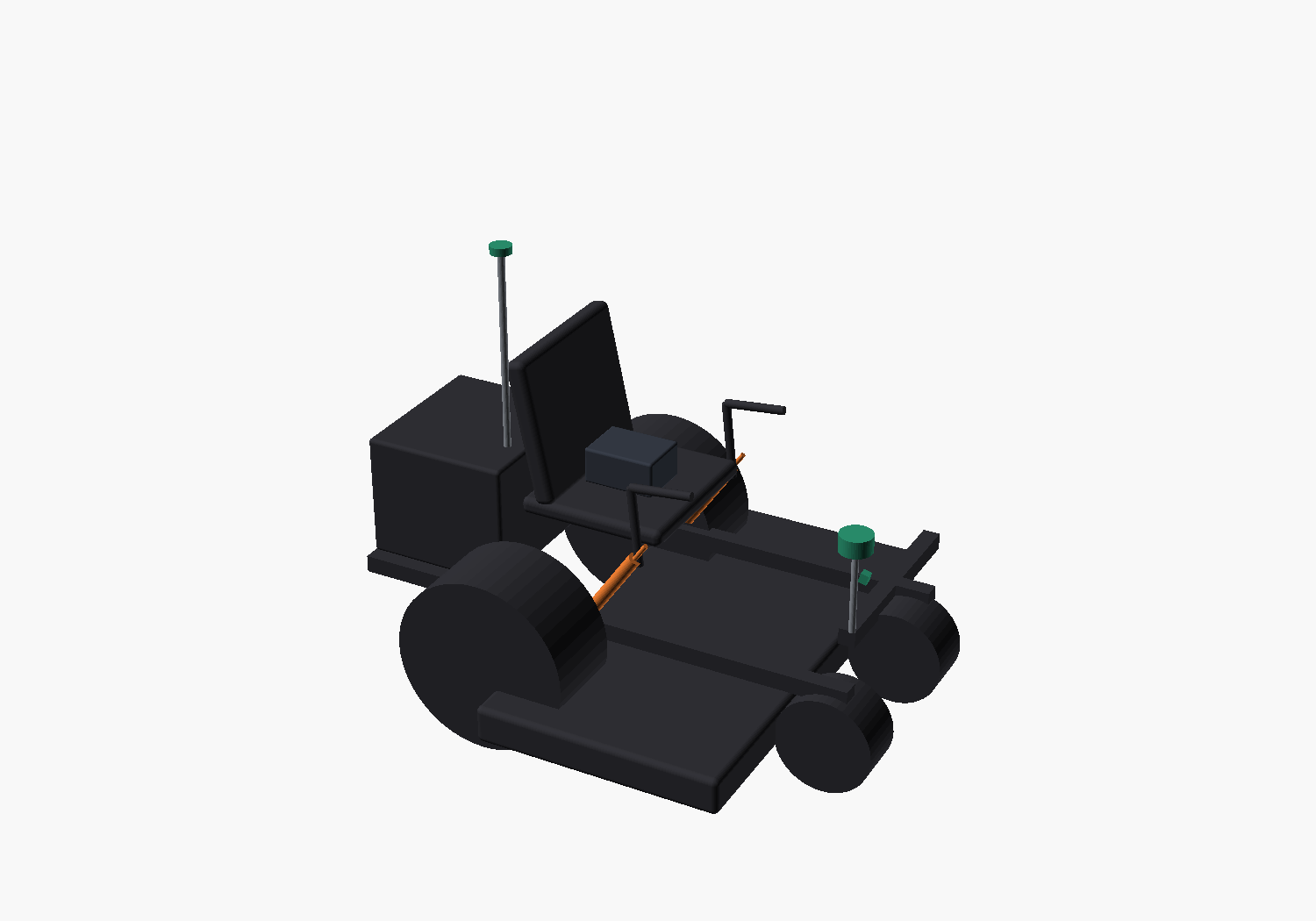
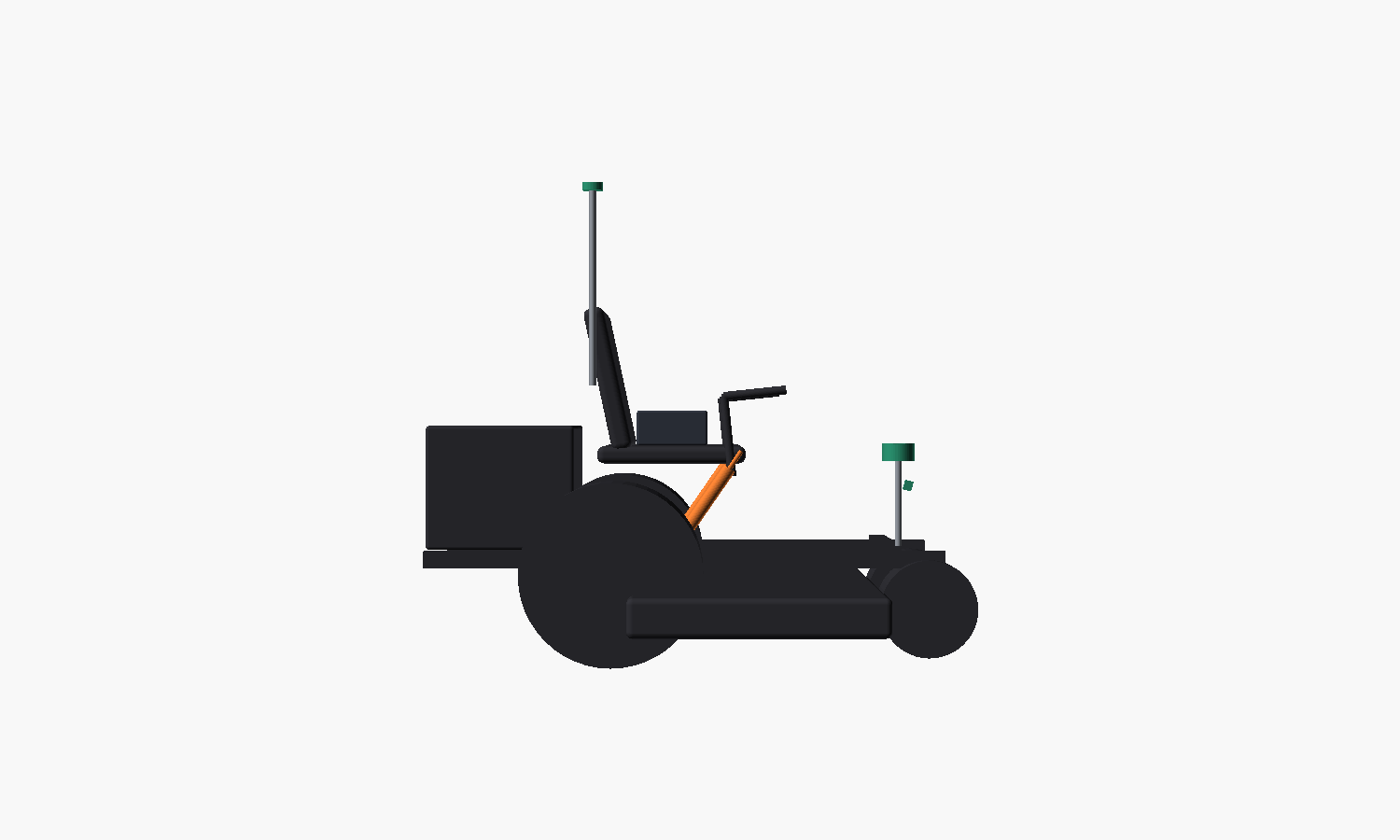
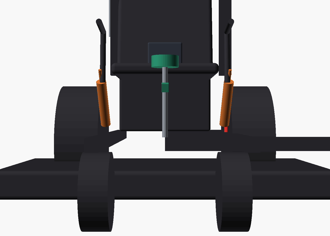
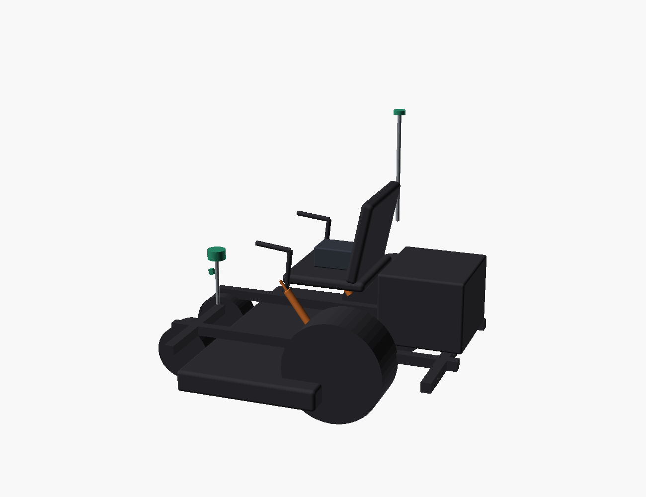
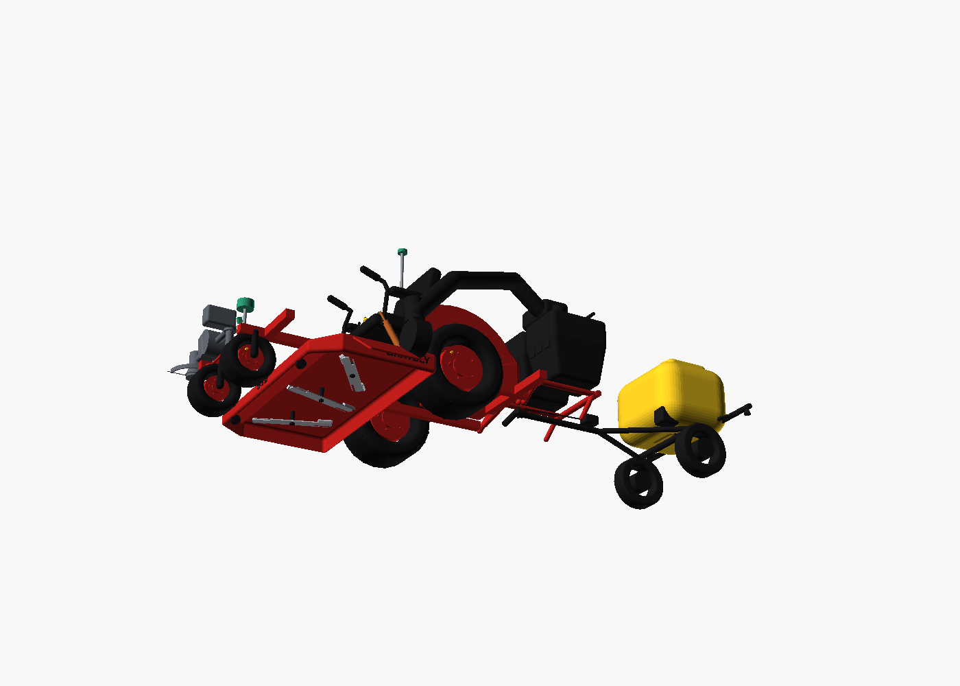
Every component is modeled to the datasheet as one parametric assembly. This is the
real exported geometry — drag to rotate, scroll to zoom. The retrofit hardware bolts onto a confirmed
Gravely ZT X 52 (2021, Kohler), itself spec-matched to the FULL published envelope —
1968 × 1610 × 1039 mm, 1321 mm deck, treaded 20×10-8 drive tyres — with the
GRAVELY and ZT X 52 lettering modeled as raised geometry, not a texture. The deck is hollow like
the real one: hover the machine and the three 460 mm blades spin on their spindles — and the
Phase-3 rig (power bagger, blower/trimmer boom, tow sprayer) rides along; pull the exploded-view slider to
see every subsystem fly out.
assembly.glb · 3.39 × 1.37 × 1.73 m · full rigdrag · scroll · pinch
loading 3D model…
0%2.6″
ACCESSORY BAYon a phone: tap the AR icon to stand it on your lawn
E-STOP PRESSED — KILL CHAIN
1 · NC mushroom contact opens the relay-coil loop
2 · PTO clutch relay drops — blades stop
3 · Drive relay drops — actuator power cut
4 · ESP32 loses its watchdog — lap bars fail to neutral
MACHINE STATE: HOLD · DISARMED · BLADE OFF — hardware first, software echoes it
The base machine — a stock Gravely ZT X 52 before the retrofitphoto: Gravely
System architecture
Three brains, one bus
Not one black box — responsibility is split across compute that's purpose-built for each
job, coordinating over MAVLink. A real-time flight controller drives and navigates; a Linux companion sees;
a microcontroller closes the analog steering loop the autopilot can't.
The Driver
Pixhawk 6C
ArduPilot Rover · skid-steer
Owns drive: throttle-left / throttle-right
RTK waypoint missions + geofence
Hardware / RC / GCS failsafe chain
Fail-to-neutral on any link loss
The Eyes
Raspberry Pi 5 + Hailo-8L
13 TOPS NPU · vision + UI host
Camera AI on the Hailo NPU, on-device
Fuses LiDAR + ultrasonic → stop verdict
Serves one web UI: iPad + on-unit kiosk
Uploads coverage missions to the FC
The Hands
ESP32
Lap-bar PID · closed loop
Reads FC PWM setpoint + 2 position pots
PID-drives both lap-bar actuators
Fails actuators to neutral on e-stop
The loop the autopilot can't run directly
PixhawkMAVLinkPi 5
Sense
Dual RTK GPS±2cm
360° LiDAR10Hz
2× camerasAI
Overhead sonar1.6m
feeds
Think
Pixhawk 6Cnav
Pi 5 + Hailovision
ESP32PID
commands
Act
Lap-bar L/Rdrive
PTO relayblades
Throttle servoRPM
The control UI · running live
The interface, not a screenshot
This is the actual planned control UI — one web app that serves both the iPad over WiFi
and the on-unit touchscreen. It's embedded here running on an in-browser telemetry simulator,
so it arms, drives a coverage route, draws the mowed trail, and reacts to live hazards in real time. Tap the
controls — they work.
LIVE — simulated telemetry
Tesla-clean, built for a touchscreen
A single status verb tells you the machine's state at a glance — PARKED → READY → MOWING — backed
by a top-down mockup that turns red when blades engage and throws an obstacle arc when something's ahead.
Teach & repeat and draw-a-zone → auto-coverage — mark keep-outs (beds, trees, spots the sonar keeps hitting); the planner fills the rows, shows m² / minutes / % covered, and uploads them as a mission.
Live OpenStreetMap with an RTK heading arrow and a green trail of exactly what's been mowed.
Front + rear AI camera feeds with grass-coverage % and live hazard boxes from the on-device model.
TILT, OVERHEAD & obstacle chips flip to warning/critical and cut the mission before the hazard.
On-screen E-STOP commands HOLD · disarm · blade-off — backing up the physical kill chain.
Precision
Centimeters, not "close enough"
The upgrade that matters is dual-antenna moving-baseline heading. One RTK
antenna gives a great position but a noisy heading at a standstill; a second antenna fixes heading
geometrically, so the machine tracks straight rows from the moment it starts.
±2 cm
Position
RTK-fixed ZED-F9P
~0.4°
Heading
moving baseline
few cm
Cross-track
row-to-row
13 TOPS
On-device AI
Hailo-8L
Teach & Repeat
Drive the path once; it repeats the RTK track. Routes persist on the Pi.
Auto-Coverage
Drive the perimeter; the planner handles L/U-shaped yards and keep-outs, adds perimeter laps, and uploads AUTO waypoints.
Overhead Clearance
Upward ultrasonic stops the machine below 1.6 m — it won't drive under low limbs.
Incline Safety
IMU pitch/roll watchdog, hard cutoff past 15°. No mowing across steep grades.
Safety
A layered kill chain
A 52" deck can kill. Safety isn't one switch — it's independent layers that each cut drive
and blades, so no single failure leaves the machine moving. Blades stay disconnected until every
layer is proven.
Physical e-stop
Normally-closed, wired in series with drive + PTO — cuts power independent of any code
RC kill switch
Independent radio cutoff for drive relay + blade relay
Software interlock
Evaluates incline (15°), overhead (1.6 m) & obstacle every cycle → cuts drive + PTO
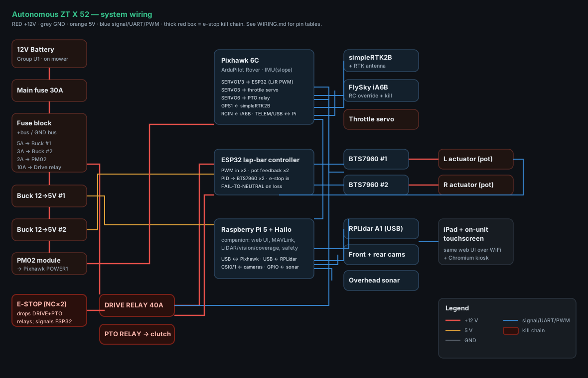
The kill chain gets wired and tested first, then power, then signal. Each branch has its own
fuse; every ground returns to one bus. This is the map — verbatim from docs/WIRING.md and the
lapbar_controller.ino pin defs.
+12 VGND5 Vsignal / data
Complete system wiring — power, the e-stop kill chain, and every signal path. open full size ↗
Power distribution
Branch
Fuse
Gauge
Feeds
Battery → fuse block
30 A
10 AWG tinned
the whole system
Buck #1 (12→5 V, 5 A)
5 A
14 AWG
Raspberry Pi 5
Buck #2 (12→5 V, 3 A)
3 A
16 AWG
ESP32, throttle servo, ultrasonic
PM02 → Pixhawk POWER1
2 A
PM02 leads
clean 5 V + battery V/I sense
Drive relay → BTS7960 V+ (×2)
10 A
14 AWG
both lap-bar actuators
PTO relay → clutch
OEM
OEM gauge
engages the deck blades
Pixhawk 6C connectors
Port
To
Signal
POWER1 (6-pin)
PM02 → battery
5 V in + V/I sense
GPS1 (10-pin UART)
simpleRTK2B
TX↔RX, RX↔TX, 5V, GND
TELEM2 / USB-C
Pi 5
MAVLink UART (or Pixhawk USB → Pi USB)
RC IN
FlySky iA6B
SBUS — manual override + kill
FMU SERVO1
ESP32 GPIO34
throttle-LEFT (skid-steer)
FMU SERVO3
ESP32 GPIO35
throttle-RIGHT
FMU SERVO5
throttle servo
engine RPM
FMU SERVO6
PTO relay coil
blade engage (fn = Relay)
ESP32 lap-bar controller — GPIO map
Pin
Net
To
GPIO34
PWM in L
Pixhawk SERVO1
GPIO35
PWM in R
Pixhawk SERVO3
GPIO36 (VP)
pot L wiper
LEFT actuator feedback
GPIO39 (VN)
pot R wiper
RIGHT actuator feedback
GPIO25
e-stop sense
E-STOP 2nd NC → GND (pull-up)
GPIO16 / 17
L_RPWM / L_LPWM
BTS7960 #1
GPIO18 / 19
L_REN / L_LEN
BTS7960 #1 enables
GPIO26 / 27
R_RPWM / R_LPWM
BTS7960 #2
GPIO14 / 12
R_REN / R_LEN
BTS7960 #2 enables
GPIO2
status LED
onboard (solid=armed, blink=failsafe)
Actuator feedback pot — PA-14P 6-pin Molex colour code
0–10 kΩ pot: +end → 3V3, wiper → ESP32 ADC, −end → GND. Solder + heat-shrink the motor + pot leads (vibration-critical); connectorize the power branches (XT60) and the Pixhawk JST-GH ports; conformal-coat every PCB + dielectric-grease every gland after testing.
Custom hardware
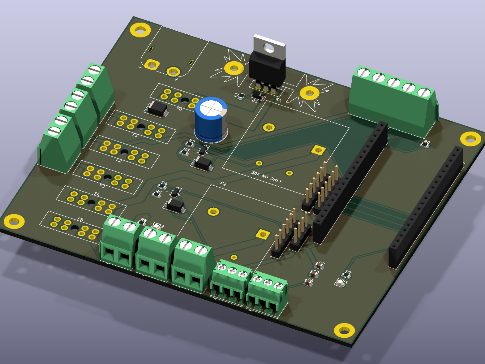
MowerCarrier — a board for the messy part
The wiring above is a rat's nest to build by hand — and the safety kill-chain is
the last thing you want to get wrong twice. So it becomes one 2-layer board: the fused power tree (20 A main,
five branches), reverse-polarity + load-dump protection, the two 30 A safety relays, and the ESP32 lap-bar controller — every
module plugs in by connector. The proven modules (Pixhawk, Pi, buck, BTS7960) stay off-board; the board is the
glue, power, and safety. It's a routed, DRC-clean KiCad project generated from one Python file — in
hardware/pcb/.
+12 V+5 V+3V3signalGND
Rev A.1, ray-traced by KiCad — power in & Q1 on its heatsink (top), fused branches (left), the two kill-chain relays (middle), ESP32 carrier (right). open full size ↗
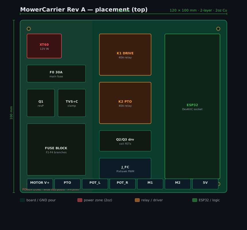
Routed copper — 120 × 100 mm, 2-layer, 2 oz Cu; the main current path is solid pours, the logic is autorouted. open full size ↗
The safety gate
Each 30 A relay energises only when the E-STOP is closed (coil high side) and the controller
commands it on (coil low side, via a MOSFET). Either one dropping cuts motor power instantly — a hardware button
press and a software fault both kill it. A second E-STOP contact signals the ESP32 for fail-to-neutral.
Honest scope
Routed and checked by the tools — ERC 0, DRC 0, schematic parity 0 — with Gerbers, pick-and-place
and an LCSC BOM. Turning the first netlist into copper caught seven real design errors (a backwards
reverse-polarity FET among them). What's left is a human pre-fab review: caliper the ESP32 row pitch and
fit Q1's insulating kit.
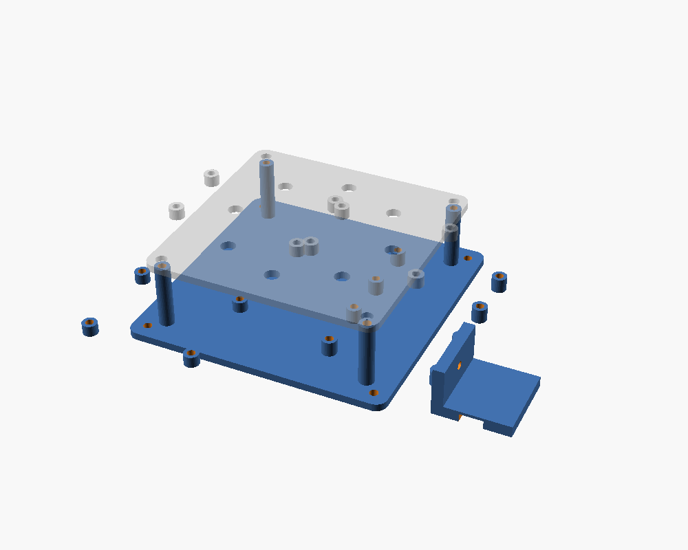
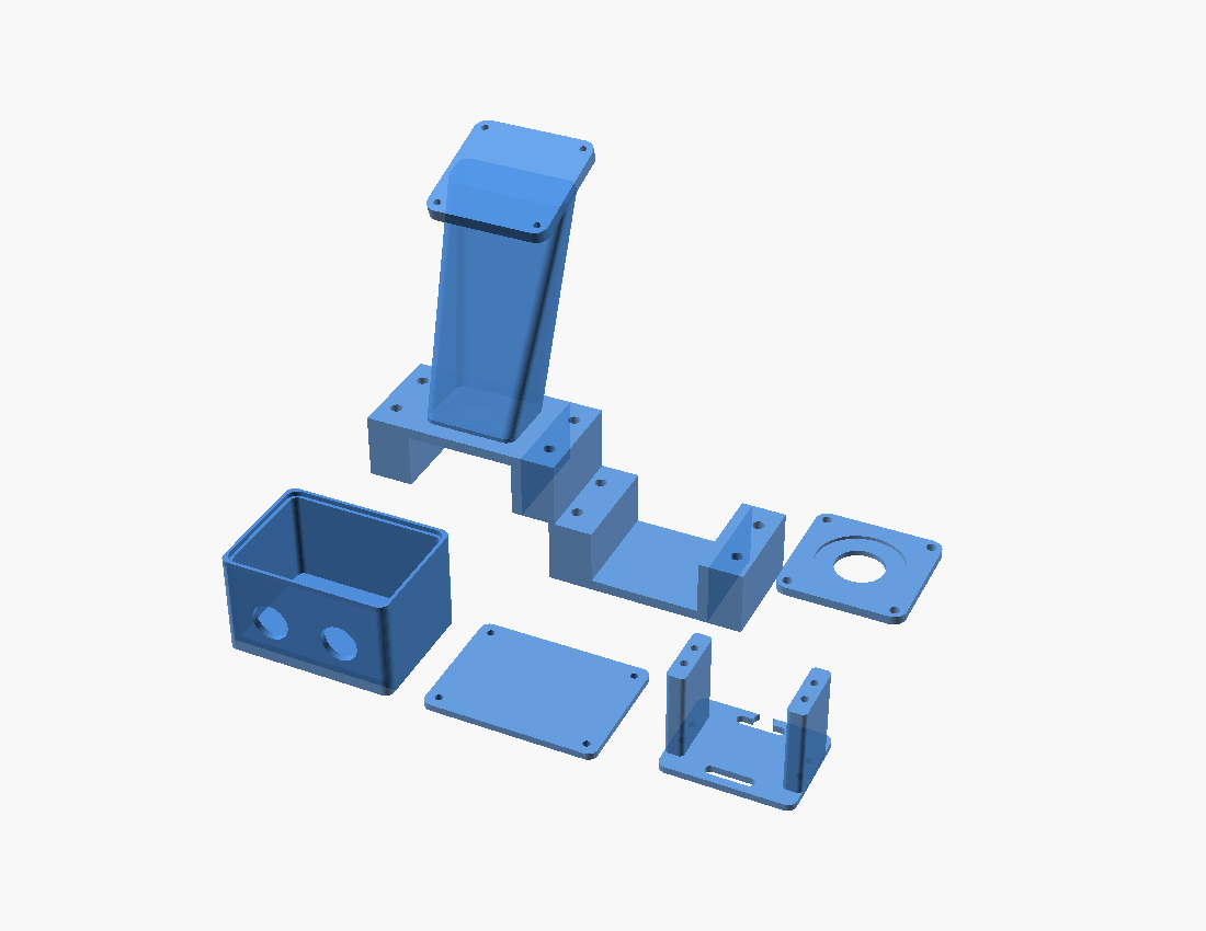
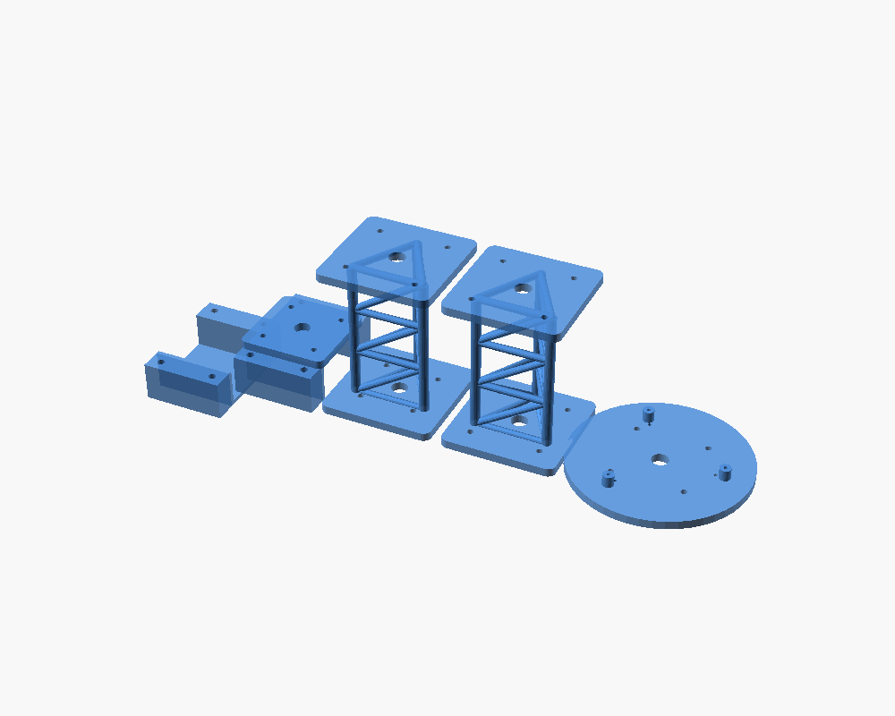
The entire mount system is one OpenSCAD model. Section 1 of params.scad holds the
only per-machine measurements — change those and re-render to fit a different zero-turn. Every printable part
is bed-fit checked and ships with a baked-in adhesion brim.
Under the hollow deck — 3 × 460 mm blades on their spindles
Seat-mounted brain box
E-stop pedestal · PTO relay
RPLidar front-mast mount
RTK antenna mast
Spec
Value
Printable parts
24, all bed-fit verified
Target printer
FlashForge Adventurer 3 · 150 × 150 mm bed
Bed adhesion
Brim welded onto every part (slicer brim off)
Material
ASA / PETG — UV + heat tolerant, outdoor
Design tolerance
SLOP 0.2 mm · clearance-fit 0.4 mm for FDM ±0.3 mm
Port to another ZTR
Re-measure params.scad §1 → re-render → re-slice
All 24 core printed parts — exact bounding boxes (+8 Phase-3 attachment brackets and 8 sensor/screen mounts in the repo gallery) ▾
Part
Bounding box (X × Y × Z)
Fits 145 mm
Enclosure foot
40.0 × 40.0 × 26.0 mm
✓
Equipment plate
140.0 × 140.0 × 38.0 mm
✓
Upper shelf
139.3 × 124.0 × 10.0 mm
✓
Lap-bar yoke (lower)
127.1 × 46.0 × 10.0 mm
✓
Lap-bar yoke (upper)
68.0 × 46.0 × 10.0 mm
✓
Frame-rail anchor (lower)
57.0 × 71.1 × 46.0 mm
✓
Frame-rail anchor (upper)
57.0 × 28.4 × 46.0 mm
✓
GPS mast clamp A
104.0 × 57.6 × 50.0 mm
✓
GPS mast clamp B
104.0 × 37.6 × 50.0 mm
✓
GPS antenna plate (ANN-MB-00, 2× M4)
96.0 × 96.0 × 24.0 mm
✓
LiDAR base A
60.0 × 88.8 × 28.4 mm
✓
LiDAR base B
64.0 × 88.8 × 34.4 mm
✓
LiDAR mast (lower)
82.0 × 82.0 × 112.0 mm
✓
LiDAR mast (upper)
82.0 × 82.0 × 112.0 mm
✓
LiDAR top plate
123.7 × 123.7 × 14.0 mm
✓
Camera base
44.0 × 44.0 × 50.0 mm
✓
Camera cradle
31.0 × 50.0 × 30.5 mm
✓
E-stop face
58.0 × 58.0 × 4.0 mm
✓
E-stop pedestal A
92.8 × 83.1 × 139.1 mm
✓
E-stop pedestal B
92.8 × 50.0 × 30.4 mm
✓
Relay box
76.0 × 56.0 × 45.0 mm
✓
Relay lid
76.0 × 56.0 × 6.0 mm
✓
Throttle-servo bracket
56.9 × 44.0 × 42.0 mm
✓
Nameplate badge
114.0 × 34.0 × 4.0 mm
✓
Auto-measured by cad/stl/export_stl.sh — every part is bbox-gated ≤ 145 mm on all axes before it ships. Brim-baked copies in stl/brim/.
Software · firmware · parts
Built and tested, end to end
Companion (Python)
HTTP + SSE telemetry, JSON control
Coverage planner & mission upload
Safety interlock + vision loop
Firmware
ESP32 lap-bar PID, fail-to-neutral
ArduPilot skid-steer params
Moving-baseline heading config
Tested
69/69 backend tests green + ArduPilot SITL end-to-end
Pure functions for safety & planning
Full wiring / pinout diagrams
Every part, with order links
Real, in-stock parts — links verified against live listings, no fabricated SKUs. Two build tiers: functional ≈ $1,644, or precision ≈ $1,812 with the dual-antenna heading kit. Amazon · Adafruit · eBay · vendor-direct where each is cheapest.
YOUR BUILD$1,644prices as verified on the order sheet, 2026-06-26
Full itemized order sheet with live prices lives in cart/ORDER.md (machine-readable ORDER-SHEET.csv). ArduSimple ships from the EU; bundle the Holybro and PiShop orders to save on shipping.
Teaching it to see
Building the obstacle brain
Off-the-shelf detectors know "car" and "dog" — they don't know a garden hose, a sprinkler
head, or a child's toy left in the grass, and they can't tell you how far. So the perception model is trained
for this job: what's in a yard, is it in my path, and how many meters away — small enough to run
entirely on the Hailo-8L, no cloud.
INPUT
Front camera
Pi Camera 3 frame, 1536×864, downscaled to a 640×384 tensor at 20 fps.
BACKBONE
MobileNetV3-lite
INT8 feature extractor, chosen to fit the Hailo-8L's 13 TOPS with headroom for two heads.
Per-pixel depth, supervised by the LiDAR so a single camera can estimate meters-to-target.
FUSION
Stop verdict
Detections × depth × LiDAR ring × ultrasonic → is a hazard in the stop-zone, and how close.
13 TOPS on-device (Hailo-8L)INT8 quantized, compiled to .hef<30 ms end-to-end, no cloudstop-zone: cx 0.28-0.72, cy ≥ 0.55LiDAR gives depth ground truth
How the model gets trained
No hand-labeling thousands of images. The machine labels its own
data: every teach-and-repeat run records camera frames with a time-synced LiDAR scan, and the LiDAR does the
hard part — it already knows where the solid things are.
01 · COLLECT
Drive & record
Teach runs capture front-camera frames + synced 360° LiDAR + IMU pose. Real yards, real light, real clutter.
02 · AUTO-LABEL
LiDAR + big model
The LiDAR ring supplies sparse depth truth; a large open-vocab model pre-labels boxes. A human only spot-corrects.
03 · TRAIN
Two-head fine-tune
Detection head on the yard classes; depth head self-supervised against the LiDAR points. Hard-negative mining on near-misses.
04 · QUANTIZE
INT8 → .hef
Post-training quantization, then the Hailo Dataflow Compiler emits a .hef for the AI HAT+.
05 · SHADOW
Validate on the machine
Runs live but blade-gated, logging every verdict vs the LiDAR. It only gets to stop the deck once precision/recall hold.
Vision is one voice, never the only one — every stop is cross-checked against the LiDAR and ultrasonic, and the blade stays disconnected until the model is proven in the field. See software/companion/vision.py.
The code that runs it
Small, pure, testable
The parts that can hurt someone are pure functions with no hardware in them, so they're
unit-tested off the machine — 25/25 green. The safety interlock, the vision verdict, the fail-to-neutral loop,
and the MAVLink mission encoder, verbatim from the repo.
companion/safety.pypython
def evaluate(s):
"""(state) -> (allow_move, reason). Single most important blocker,
checked in strict priority order. Pure + unit-tested."""
if s.get("estop"):
returnFalse, "E-STOP"
slope = slope_of(s.get("roll"), s.get("pitch"))
if slope > MAX_SLOPE_DEG: # 15 deg rollover cutoffreturnFalse, f"too steep ({slope:.0f} deg)"
oh = s.get("overhead_m")
if oh is notNoneand oh < MIN_OVERHEAD_M:
returnFalse, f"low branch ({oh:.1f} m)"if s.get("obstacle"):
returnFalse, "obstacle ahead - holding"returnTrue, None
Layered safety interlock. One function, strict priority: e-stop > slope > overhead > obstacle. Whatever the AI thinks, this has the last word.
companion/vision.pypython
def evaluate(detections):
"""PURE. detections: [{cls, conf, box:[cx,cy,w,h]}...]
-> (obstacle, range_m, objects, grass_pct)."""
hazards = [d for d in detections
if d["cls"] in HAZARD and d["conf"] >= CONF_MIN
and _in_stop_zone(d["box"])]
if hazards:
nearest = max(hazards, key=lambda d: d["box"][1]) # largest cy = closest
range_m = round((1.0 - nearest["box"][1]) * 6.0 + 0.4, 1)
returnTrue, range_m, objects, grass_pct
returnFalse, None, objects, grass_pct
Vision verdict. A hazard only stops the machine if it's in the path stop-zone; range is estimated from where it sits in frame.
firmware/lapbar_controller.inoc++
void loop() {
bool estop = digitalRead(PIN_ESTOP); // HIGH = NC openedbool lostL = (now - lastEdgeL) > FAILSAFE_MS; // FC signal lost?bool fail = estop || lostL || lostR;
// fail -> command bars to CENTER, then cut the bridges (coast to neutral)int tgtL = fail ? (POT_L_MIN+POT_L_MAX)/2 : targetFromPwm(pulseL);
if (fail) {
drive(step(pidL, tgtL, potL)); // PID toward neutralif (centered) disableAll(); // FAIL-TO-NEUTRAL
}
}
Fail-to-neutral. The ESP32 the autopilot can't be: lose the signal or trip the e-stop and it drives the bars to center, then coasts.
companion/mav.pypython
def to_mission_items(waypoints):
    """[[lat,lon]...] -> MISSION_ITEM_INT (NAV_WAYPOINT).
    lat/lon scaled to 1e7 ints as MAVLink requires. Unit-tested."""
    return [dict(seq=i, command=MAV_CMD_NAV_WAYPOINT,
                 current=1 if i == 0 else 0, autocontinue=1,
                 lat=int(round(lat * 1e7)),
                 lon=int(round(lon * 1e7)), alt=0.0)
            for i, (lat, lon) in enumerate(waypoints)]
Mission upload. Coverage rows become ArduPilot AUTO waypoints — lat/lon scaled to the 1e7 ints MAVLink expects.
How it was built
Engineered with an AI agent loop
A build this broad — mechanical, electrical, firmware, ML, safety — normally takes a team.
It was done solo by driving AI agents hard and precisely: decomposing the problem, constraining every prompt,
and verifying the output instead of trusting it. The prompt engineering was the multiplier.
Decompose, then parallelize
Split the machine into subsystems with hard interfaces, then ran research agents in parallel — one sourcing RTK, one the actuators, one the safety chain — each with its own acceptance spec.
Constrain to the datasheet
Every CAD prompt carried exact dimensions and a bed-fit rule; parts that overhung the 150 mm printer were rejected by an automated gate, not by eye.
Verify, don't trust
Dead ASINs caught by cart-math, an IP-rating error caught by re-reading the datasheet, XSS caught in review — outputs were adversarially checked before they shipped.
a representative sourcing prompt — constraint + verification, not vibes
You are sourcing the linear actuators for a bladed outdoor robot.
Constraints: 12V, ≥150 lbf, ≥100mm stroke, IP65+, with a
position-feedback potentiometer (closed-loop steering). Verify each
part on its live page - never invent an ASIN or a spec. Return a
table: part, real link, price-read-off-page, and the one spec that
would disqualify it. # flagged the PA-14P: genuine IP54, not IP66 -> needs a rod boot
generating a printable part — parametric + self-checking
Write the LiDAR mount in OpenSCAD, fully parametric off params.scad.
The RPLidar A1M8 base is a teardrop 96.74 x 70.28 mm with a
4-hole trapezoid bolt pattern - NOT 3 holes on a circle
(verify against the datasheet drawing). It must split to fit the
150 mm bed and print without supports. # caught: my first pass
assumed 3 holes on a bolt circle - the datasheet drawing showed a 4-hole trapezoid.
forcing verification into the loop
After every STL export, run export_stl.sh and reject any part whose
bounding box exceeds 145 mm on any axis. Don't eyeball it - fail the build
and tell me which part and by how many mm. # this gate caught the
equipment plate at 179.5 mm and the e-stop pedestal at 145.1 mm before they ever printed.
The pattern throughout: tight constraints in, structured output back, an automated or adversarial check before it counts. That's what let one person carry a multi-subsystem robotics build end-to-end.
Down to the millimetre
Every number that matters
The whole kit is parametric off one file — so it has to be exact. These are the real,
sourced dimensions the CAD is built from: the machine, the parts that bolt to it, and the tolerances the printer
actually holds. Change SECTION 1 of params.scad and it re-fits any zero-turn.
Adapt it to YOUR mower — enter 6 measurements, get your SECTION 1
The worksheet is
docs/MEASURE.md
(10 minutes with a caliper). Type your numbers and copy the block into cad/params.scad —
all 32 brackets re-generate to fit your machine. Prefilled with the Gravely reference values.
The machine — Gravely ZT X 52
Overall (Kohler 915256)
1968 × 1610 × 1039 mm (L×W×H)
Curb weight
615 lb (279 kg)
Cutting deck
1321 mm (52″), 11-ga fabricated
Rear drive wheels
20×10-8 → Ø 508 mm, 254 mm wide
Front casters
11×6-5 → Ø 279 mm
Wheelbase
1170 mm (derived from the 1968 mm overall; tape-measure to confirm)
Nothing here was right the first time. The loop is model → render → measure against the
spec sheet → find what's wrong → fix → re-export, and every iteration maps to a real commit. The full log —
including the constraints A–Z that actually bit — lives in
docs/DESIGN-LOG.md.
Two parts didn't fit the printer
equipment plate + e-stop pedestal exceeded the 150 mm bed → resized, then an automated bbox gate so it can't regress
Both actuator listings 404'd
agent-sourced ASINs rot — every order line re-verified on its live page before it counts
The lidar plate was wrong
RPLidar's base is a teardrop with a trapezoid bolt pattern, not a circle — caught by a datasheet pass, plate redesigned
The 3D model was grey
split the CAD into colour groups (red paint / rubber / retrofit metal) and rebuilt the site model multi-material
Machinists can't cut STL
OpenSCAD can't export STEP → built a DXF pipeline for flat parts + a mesh-sew STL→STEP converter for the rest
The width was 144 mm short
a 52″ deck's shell is wider than its cutting width — shell 1400 mm + 264 mm deflector = exactly the published 1610 mm
The deck ate the tyres
at a 900 mm wheelbase the deck geometrically can't fit between the axles → wheelbase re-derived (1170 mm) from the published 1968 mm overall length
A sphere floated mid-air
a rounded-box helper with radius > half a dimension leaves a stray minkowski sphere — found hovering beside the deck in a render
The blades had nowhere to live
the deck hull was solid → hollowed underneath like the real shell; three 460 mm blades on real spindles, spun by a baked glTF animation
Every CAD source, drawing, and supplier is researched, verified, and logged — so the build
is buildable by anyone. The retrofit parts print in ASA/PETG today; the same files go out to a metal shop when
it's time to machine them in aluminium. Full sourcing sheet in
docs/SOURCING-AND-FABRICATION.md.
Flat parts (e-stop face, relay lid, plates) go out as DXF for laser cutting (cad/dxf/); 3D mounts as STEP solids for CNC (cad/step/, generated from the STLs by stl_to_step.py). General tolerance ISO 2768-m / ±0.005″; anodize for outdoor.
Prototype plan: flat brackets as DXF at OSH Cut + 3D mounts as STEP at SendCutSend / Protolabs — or the whole 24-part mixed order through SendCutSend / eMachineShop (US, no minimum).
Fabrication package — ready to send
The full quote package is generated and downloadable: 8 flat parts as DXF, 8 dimensioned drawing PDFs (title block, material, tolerance, finish), and 16 CNC parts as solid STEP — machinable geometry, not raw mesh. Grab everything in one click, or pick individual files, then upload straight into any supplier's instant quoter.
Ballpark cost (public instant-quote rates, 6061-T6, qty 1, prototype — indicative, not a live quote):
Group
Parts
Process
Typical each
Group est.
Flat / laser
8 DXF
Laser-cut sheet
~$8–30
~$120–220
CNC 3-axis
16 STEP
Milled from billet
~$35–120
~$700–1,300
Full prototype set (+ ~$29 order min, anodize, shipping)
~$900–1,600
Numbers are indicative of published SendCutSend / OSH Cut / Xometry rates — a binding price needs the files run through the supplier's own quoter under an account (a manual, human-in-the-loop step, not automated here). Every file above is upload-ready today.
Phase 3 — the whole rig
One brain, every yard tool
Once the machine holds ±2 cm lines at a controlled speed, every implement inherits that
precision. Mowing was the beachhead — the same navigation stack now carries a self-dumping power bagger,
a rotating blower + string-trimmer boom, a 30-gal tow sprayer with speed-perfect application, TPMS
on all four tyres, and an ignition sequence so the machine starts itself. Design + tested policy layer today,
hardware with the build — spec in
docs/ATTACHMENTS.md.
Power bagger — dumps itself
Twin rear bins + deck duct (the Gravely Power Bagger / Exmark UltraVac pattern) with the manual lever replaced by an electric dump actuator. Fill is estimated from blade-time × camera grass coverage; the dump cycle is interlocked — stopped, blades off — so fall cleanups become: mow, drive to the pile, dump, resume. All by itself.
Blower + trimmer boom — edging & blowing
A slew-ring boom on the front corner carries a high-CFM blower volute and a string-trimmer head. The trimmer is gated exactly like a blade: armed only, ≤ 1 m/s, killed by the e-stop. Edging passes are just RTK routes along the geofence line with the boom pointed down.
FIMCO 30-gal sprayer — speed-perfect dosing
The 12 V pump follows ground speed: half speed = half flow = identical litres per square metre, and the pump pauses above 25°/s of yaw so headlands never get the double dose that burns herbicide stripes. Tank level, duty and litres applied stream in telemetry.
TPMS + ignition + hour meter
Valve-stem pressure sensors on all four tyres (a low tyre un-levels the deck and waves the cut long before it looks flat). The starter relay cranks the Kohler with temperature-scheduled choke and hard interlocks — PTO off, e-stop clear, ≤5 s crank — and the e-stop grounds the magneto. Engine hours persist; oil and blade service countdowns live on the dash.
The perfect turn — why this machine never pivots
A zero-turn pivot spins one wheel forward, one backward, in place — all of the yaw moment passes
through two small contact patches as shear on the turf. Under 615 lb the root mat gives way and you
get the classic ZTR divot at every row end. Keep both wheels rolling and the same manoeuvre transmits as
rolling friction instead of shear — orders of magnitude gentler. So the coverage planner never pivots:
Row spacing ≥ 2r
Smooth U — 90° arc, straight crossover, 90° arc; both wheels roll forward the whole time (the outside wheel just travels further)
Row spacing < 2r
3-point K-turn (the tractor headland turn) — 90° arc out, straight reverse of 2r−spacing while the tail swings, 90° arc onto the next row; three gentle segments instead of one violent twist
Headlands
rows are inset by the turn radius so every turn stays inside the geofence; r = 1.2 m — the gentlest arc the ZT-2200 hydros hold accurately
The result
teardrop row-ends on the map instead of black semicircles of dead turf — and a sane drawbar angle when the sprayer is hitched
Implemented + tested: missions.plan_coverage_turns · geometry, headland containment and interlocks in the 69-test suite.
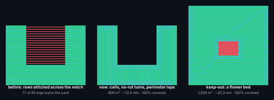
Real yards aren't rectangles
The first planner swept rows across the whole
boundary and stitched each row's pieces together — fine on a rectangle, but in an L- or U-shaped yard the leg
between pieces drove straight across the gap, which in a real yard is a flower bed or the house. Now the rows
are grouped into cells that can each be mowed back and forth, rows run in whichever direction needs the
fewest turns, every leg is checked and
routed around anything in the way, keep-outs (beds, trees, the shed — or a spot the sonar keeps
stopping at) are holes in the plan, and the strip the no-rut turns need is mowed last as perimeter laps.
Every plan reports its area, time and measured % covered (the deck swept along the path on a 10 cm
grid) before the machine moves — across eight test yard shapes, nothing leaves the yard and coverage is 99.9–100%.
Drawn by the real planner (scripts/plan_figure.py) — 40 × 40 m lawn with a bed: 1,530 m², ~22.3 min, 100% covered.
Watch it happen
Build videos — rails ready, camera pending
One short video per build phase lands here as the physical build progresses. The design is done on screen; this section is where it gets real.
Phase 1 — bench brain-box bring-up
RTK fix on the bench · first UI connect — coming with the build
Phase 2 — kill chain + lap bars
meter on the mushroom · bars centering on stands — coming with the build
Phase 3 — first autonomous pass
teach-and-repeat, blades off, open field — coming with the build
Straight answers
The questions everyone asks
Will it really mow unattended?
Not on day one, by design. Blades stay physically disconnected until drive, RTK navigation, and every failsafe is proven — jack stands first, then open-area driving, then supervised mowing. The commissioning sequence is a hard go/no-go checklist in docs/BUILD.md, and the whole build is operator-supervised R&D, not a consumer appliance.
Why not just buy a robot mower?
Consumer robots are electric toys next to a 615 lb commercial zero-turn with a 52″ fabricated deck — different cut quality, different acreage, different machine class. The commercial autonomy options (Greenzie, Scythe) run ~$25k+ or lease-only. This retrofit is ~$1.6–1.8k on top of a mower you already own.
Does it fit my mower?
Any lap-bar zero-turn, in principle. Every machine-specific dimension lives in SECTION 1 of cad/params.scad — measure five things (lap-bar tube, spacing, travel, frame rail, seat) and the brackets re-generate to fit. The reference build is a Gravely ZT X 52.
What does it actually cost?
≈ $1,644 functional, ≈ $1,812 with the dual-antenna heading upgrade — from a live-verified order sheet, not estimates. The configurator above breaks it down; the RTK GPS is the one cost you shouldn't trim.
What happens in rain?
The brain lives in an IP67 enclosure with cable glands; boards get conformal coating; connectors get dielectric grease; the one IP54 weak point (the actuator rod) gets a boot. It's built to live outdoors — but wet-grass mowing is a traction/safety call the incline monitor treats conservatively.
Why open-source something with blades?
Because the safety architecture is the most valuable thing to share: a hardware-AND-software kill chain, fail-to-neutral firmware, and a commissioning sequence that assumes failure. The commercial path (mowing-as-a-service on controlled sites) keeps liability where it belongs — with a trained operator, not a kit customer.
Where this sits in the landscape
Machine class
Approach
Cost character
You own it?
This retrofit
615 lb commercial gas ZTR you already own · 52″ steel deck
open-source ArduPilot retrofit — CAD, firmware, PCB, docs all public
≈ $1.6–1.8k in parts on top of your mower
Yes — MIT, yours
OpenMower / Ardumower
consumer robot-mower conversions — light, plastic-deck class
open-source, excellent community
hundreds of dollars
Yes
Greenzie
commercial mowers via OEM/partner integrations
proprietary retrofit software
enterprise / fleet pricing (undisclosed)
Licensed
Scythe M.52
purpose-built electric autonomous 52″
proprietary, mowing-as-a-service
pay-per-acre service model
No — service
Husqvarna CEORA
commercial wire-free robot (EPOS RTK)
proprietary systematic robot, small-blade deck
premium commercial, dealer-priced
Yes
Characterizations from public positioning as of mid-2026; undisclosed pricing left undisclosed. The honest differentiator: everyone else either converts a toy or sells a closed platform — this puts open autonomy on the class of machine that already cuts real acreage.
Open source & what's next
Build it yourself — or scale it
The whole project is open source under the MIT License — CAD, firmware, control
software, the carrier PCB, wiring diagrams, and the build manual. Most open-source mowers convert a
toy robot-mower; this retrofits a 615 lb commercial gas zero-turn — which is what makes it reproducible on any
ZTR and opens a path toward robot-mowing-as-a-service for commercial grounds and solar-farm vegetation management.
Source repository
Everything: cad/ · software/ · firmware/ · hardware/pcb/ · docs/ · cart/. Clone it, edit one params file, and print. MIT · 69/69 tests · 40 print-ready parts · carrier-board design package.
Design, CAD, firmware, control software, and docs are complete and verified — and the machine is currently being built in person. Parts on order, brackets printing, wiring the kill-chain first. A multi-month, safety-gated build, documented as it happens.
Join the build — it's a community thing
Building a different zero-turn? That's the most valuable contribution — a new machine profile makes the whole
project more reproducible. Show your build, ask questions, or follow the devlog in GitHub Discussions. This
project stands on a great open ecosystem — go star them too.